
Service Manual


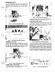


REVERSE IDLER
Grease reverse idler shaft and slide idler on shaft,
with washers. Install the shaft and tighten bolt to
80-90 in. Ibs. (9.2-10.4 Nm), as shown in Fig
15.
FIG.
15.
Reverse Idler Installation
INTERMEDIATE SHAFT
Apply a light coating of grease to the intermediate
shaft. Assemble intermediate shaft components in the
order shown in Fig. 16, and secure with E-rings. In-
stall the shaft in the upper case half, being sure to
engage
shift
forks with clutch collars. Tabs on bear-
ings must be placed in case half notches. Check shaft
end play, which should be .020-.030 in. (5-.8 mm).
Use shims in locations shown in Fig. 19
to
adjust end
Play.
FIG.
16.
Intermediate
Shaft
Assembly Order
DIFFERENTIAL
&
AXLES
If
bevel gears were removed from axles, press
gears on axles and secure with snap rings. The sharp
edge of the snap ring should face away from the
gear. Grease short cross shafts, slip bevel gears on
the shafts, and slip into slots in differential bull gear.
Assemble reduction gears, spacer and felt seal on
RH
(long) axle and install in case half
so
bevel gear
engages bevel gears in differential (Fig.
17).
FIG.
17.
Axle
&
Differential Assembly
Slide shim washer and felt seal on short axle shaft.
With the index and middle fingers of the left hand,
hold the differential bevel gears outward. While hold-
ing the assembly firmly against the installed axle
gear, carefully raise the differential until the opposite
axle gear can be engaged with the differential bevel
gears.
If
the entire assembly will not drop into place
in the case, repeat the procedure, reindexing the gear
on the short axle with a differential bevel gear one
tooth at a time (Fig. 18).
INSTALL
IN
CASE
HALF
FIRST
FIG.
18.
Axle
&
Differential Installation
INTERMEDIATE SHAFT
FIG.
19.
Shaft End Play Measurements
Shim the short
(LH)
axle shaft for the minimum end
play that
still
permits free rotation of the axle/ differ-
ential gears.
13