
Operator's Manual


4
12. Use the right tool for the job. Do not use the
Trimmer for any job that is not recommended by
Toro.
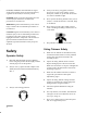
Safety and Instruction Decals
Safety decals and instructions are easily visible to the operator and are located near
any area of potential danger. Replace any decal that is damaged or lost.
ON SHAFT
(Part No. M221501)
ON SHAFT
(Part No. M221502)
Assembly
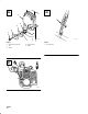
Assembling Engine and Drive
Shaft Assembly
The drive shaft, clutch drum housing and gearcase are
assembled. Attach the clutch drum housing to the
engine using the four M5 x 20 or M6 x 20 screws
supplied with the unit (Fig. 5).
Loop Handle Installation
The loop handle kit contains a package of four screws
and nuts, a rubber sleeve and the bottom clamp for
the loop handle (Fig. 6).
1. Slip the rubber sleeve around the shaft
approximately 9 inches (22.8 cm) from the end
of the stop switch/throttle trigger assembly for
an initial handle position (Fig. 6).
2. Rotate the rubber sleeve so the split is to one
side (Fig. 6).