
Operator's Manual


13
Assembly
Connecting the Attachment to the
Upper Shaft
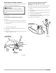
See Figure 2.
Follow these steps to connect the attachment to the upper
shaft.
1.
Loosen the knob by turning it counterclockwise.
2.
Remove the end cap from the attachment shaft.
3.
Align the button on the attachment shaft with the guide
recess on the upper shaft.
4.
Slide the attachment shaft into the upper shaft until the
attachment shaft clicks into place.
Note:
You may need to turn the attachment shaft to
properly align the two shafts.
5.
Tighten the knob securely by turning it clockwise.
Figure 2
Figure 3
Removing the Attachment from the
Upper Shaft
See Figure 2.
Follow these steps to remove the attachment from the upper
shaft.
1.
Loosen the knob by turning it counterclockwise.
2.
Push the button while pulling out the attachment.
Attaching the Front Handle
See Figure 3.
Follow these steps to attach the front handle.
1.
Remove the slotted Torx™ screws to separate the
handle from the handle support.
2.
Press the handle onto the top of the upper shaft, no
less than 10 in. (25.4 cm) from the center of the trigger
handle, angling the handle toward the trigger handle.
3.
Place the handle along the upper shaft to a position that
allows for comfortable operation.
4.
Place the handle support on the bottom of the tube on
the opposite side of the front handle.
5.
Secure the handle with the slotted Torx™ screws.
Attaching the Shoulder Strap
Model Nos. 51990
See Figure 4.
Follow these steps to attach the shoulder strap.
1.
Connect the latch on the strap to the hanger bracket.
2.
Adjust the strap to a comfortable position.
Note:
To quickly release the product from the shoulder
strap, sharply pull the quick release tab.
Figure 4
Assembly
Button
Attachment
Shaft
Guide
Recess
Upper
Shaft
Knob
Slotted
Torx
Screw
Front
Handle
Trigger
Handle
Barrier Bar
(Model Nos.
51990
Handle
Support
Strap
Latch
Hanger
Bracket
Quick
Release
Tab