
Operator's Manual


g265377
g265376
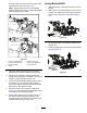
Figure28
1.Mainarm6.Framemountingbracket
2.Bolt(5/8x2inches)7.Washer(5/8x1-3/4
inches)
3.Washer(5/8x3inches)
8.Lockwasher
4.Washer(11/16x3inches)9.Nut(5/8inch)
5.Bronzebushing
1.Movetheaeratortothetransportposition;refer
toUsingtheAerator(page12).
2.Checkthatthe6mainarmspivotfreely(Figure
28).
3.Ifamainarmbinds,performthefollowingsteps:
A.Loosenthespringtension;refertoAdjusting
theSprings(page16).
B.Removethebolt,nut,washers,and
bushing,thatsecurethemainarmtothe
framemountingbracket(Figure28)and
checkthehardwareforwear.
Note:Replaceallwornordamaged
hardware.Thebronzebushingis3mm(1/8
inch)longerthanthecombinedmainarm
andmountingbracketplatethickness.
C.Assemblethemainarmtotheframe
mountingbracketwiththebolt,nut,
washers,andbushing(Figure28).
D.Tightenthebolt(5/8x2inch)andnut(5/8
inch)againstthebushings,notthearms,to
allowittopivotfreely.
E.Adjustthespringtension;refertoAdjusting
theSprings(page16).
AdjustingtheSprings
Thepurposeofthespringsistodistributetheweight
evenlyandreducetheshockloadonthepivotpoints.
Adjustthespringsevenlyacrosstolevelthemachine.
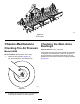
Usethenutsattopofthespringrodtoadjustthe
springtension(Figure29).
Important:Whenadjustingthespringtension,do
notcompletelycompressthecoilsare.Allowat
least1.6mm(1/16inch)ofspacebetweencoils.
g265341
Figure29
1.Springrodnuts3.1.6mm(1/16inch)
minimumspace\between
coils
2.Spring
CheckingtheTines
ServiceInterval:Beforeeachuseordaily
Toobtainmaximumaeratingperformance,always
checkthetinesforwearanddamagebeforeevery
use.Severelyworntinesareeasytobendorbreak
andleavethecoresintheground.SeeFigure30for
examplesoftinewear.
16