
Service Manual


Relays
g234235
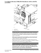
Figure28
1.Startrelay
4.Nozzlerelay2
2.Controltower
5.Nozzlerelay1
3.Mainpowerrelay
TheelectricalsystemoftheProForceDebrisBloweruses4identicalelectrical
relaysthathave5terminals.Atagneartherelaywireharnessconnectorcan
beusedtoidentifyeachrelay.
Themainpowerrelayisusedtoprovideelectricalpowertothemachine.When
thekeyswitchisintheRUNorSTARTposition,themainpowerrelayisenergized.
Thestartrelayisusedintheenginestartingcircuittoprovideacurrentpath
toenergizetheenginestartersolenoid.Onmachineswithawirelessremote
(model44552,44552TE,and44553)thestartrelayisenergizedbytheTEC
whenanenginestartsignalisreceivedfromthehandheldremote,orwhen
thekeyswitchissettotheSTARTposition.Onmachineswithatethercontrol
box(modelNo.44554)thestartrelayisenergizedwhenthekeyswitchisset
totheSTARTposition.
The2nozzlerelaysareusedforenergizingthenozzlerotationmotor.On
machineswithawirelessremote(model44552,44552TE,and44553)therelays
areenergizedbytheTECwhenanozzlerotationsignalisreceivedfromthe
handheldremote.Onmachineswithatethercontrolbox(modelNo.44554)the
relaysareenergizedwhenthenozzledirectionswitchispressedfornozzle
rotation.
Therelaysaresecuredtotherearofthemachinecontroltower.
ElectricalSystem:TestingtheElectricalComponents
Page5–24
ProForce®DebrisBlower
18237SLRevB