
Service Manual


KeySwitch(forModels44552,44552TE,and44553)
g279128
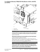
Figure22
1.Controltower
2.Keyswitch
POSITIONCLOSED
CIRCUITS
OFF
1+6,4+5
RUN1+3+4+5+6
START
1+2+4+5+6
Thekeyswitchonthemachinecontroltowerhasthree(3)positions−OFF ,RUN
andSTART.ThekeyswitchisaninputusedbytheTECandRF2CANmodule
tomanagevariousmachinefunctions.ThekeyswitchispartoftheEnergize
toRun(ETR)circuit.
TestingtheKeySwitch
IftheETRcircuit(includingthekeyswitch)isfunctioningproperly,thediagnostic
lightonthemachinecontroltowerwillilluminatewhenthekeyswitchissetto
theRUNposition.Iftestingdeterminesthattheswitchandcircuitwiringarenot
functioningcorrectly,proceedwiththefollowingtestprocedure:
1.Parkthemachineonalevelsurfaceandstoptheengine.
2.Disconnectthebatterynegative(-)cableatthebattery.
3.Disconnectthewireharnessconnectorfromtheswitchandremovethe
switchfromthecontroltowerifnecessary.
Note:Keyswitchterminals1and6areconnectedinternally.Terminals4
and5arealsoconnectedinternally.Theseterminalsshouldhavecontinuity
regardlessoftheswitchposition.
ProForce®DebrisBlower
Page5–17
ElectricalSystem:TestingtheElectricalComponents
18237SLRevB