
Operator's Manual


5
AdjustingthePTOShaft
Length
NoPartsRequired
Procedure
Important:AlongPTOshaftissuppliedwiththe
machinetoaccommodatelargevariationsinthe
tractor’sPTOand3-pointlocations.Formost
machines,thisshaftistoolongandmustbecut
tothecorrectlength,ordamagemayresult.
Important:IncorrectPTOshaftlengthcancause
machineand/orattachmentdamageandpersonal
injury.
1.Withthebloweronalevelsurface,lowerthe
bloweruntiltheinputshaftisapproximatelythe
sameheightasthetractorPTOshaft.
Note:Thisistheshortestdistancebetween
the2shafts.
2.Measurethedistancefromthelockgrooveof
thetractorPTOshafttothelockgrooveatthe
blower-inputshaft.
Note:Recordthisdimension.
3.FullycollapsethePTOshaftandmeasurethe
distancebetweenthelockpincollars.
Note:Recordthisdimension.
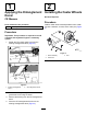
4.Attheshortestlengthoftheshaft,the2halves
ofthePTOshaftmusthaveatleast37mm
(1-1/2inches)ofadditionalclearancetocollapse
(Figure5).
Note:Ifthedimensioninstep2isnotatleast
37mm(1-1/2inches)greaterthanthedimension
instep3,thePTOshaftistoolong;proceedto
step5.Ifthereisenoughclearancetoallowthe
PTOshafttocollapse,proceedtostep10.
g011993
Figure6
1.PTOshaft2.37mm(1-1/2inches)
dimension
5.Usethefollowingcalculationtoestablish
howmuchshortertheshaftmustbe,when
connected,toensureaclearanceof37mm
(1-1/2inches):
A.Subtractthedimensionrecordedinstep3
fromthedimensionrecordedinstep2.
Note:Recordthisdimension.
B.Subtracttheresultinstep5Afrom37mm
(1-1/2inches).
Note:ThePTOshaftmustbeshortened
bythisamount.
6.Cuttheguardsandthesteeltubesshorterby
thecalculatedlength.
Note:CutbothhalvesofthePTOshaft.
7.Deburrtheendsofthesteeltubesinternallyand
externally.
8.Removealldebrisfromthetubesections.
9.Greasethesteeltubes.
10.AssemblethePTOshaftandsecureittothe
blowerandtractor.
11.Measuretheshaft.
Note:Ifitisnotatleast37mm(1-1/2inches),
repeattheprocedure.
12.Raisetheblowertothehighestposition.
Note:Theremustbeatleast75mm(3inches)
ofoverlapofthehalves.Adjustthe3-point-lift
stop,ifnecessary;referto8Adjustingthe
3-Point-LiftStop(page9).
8