
Installation Instructions


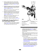


g201934
Figure140
FoamMarkerKits2017andLater
1.Tubing—foam-marker
nozzle(right-spray
section)
4.Cableties
2.Tubing—foam-marker
nozzle(left-spraysection)
5.Connectionpanel
(foam-markercompressor)
3.R-clamp
2.Routethetubesforwardalongtheleftsideof
thesprayertank(Figure140).
3.Securethetubesfortheleftandright
foam-markernozzlestothesprayerhoseswith
4cabletiesasshownonFigure140.
4.Securethetubesfortheleftandright
foam-markernozzlestothetubesforthe
agitationwith2cabletiesasshowninFigure
140.
InstallingtheLiquidandAirTubes
attheCompressor
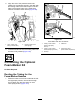
FoamMarkerKits2017andAfter
1.Routethefoamtubesfortherightboomas
showninFigure141.
g197746
g266328
Figure141
1.Bluetube
6.Cabletie
2.Airtting(left-spray
section)
7.Electricalconnector
3.Liquidtting(left-spray
section)
8.Liquidtting(right-spray
section)
4.Foamtubes(left-spray
section)
9.Cleartube
5.Foamtubes(right-spray
section)
10.Airtting(right-spray
section)
2.Insertthecleartubeintotheairttingattheside
compressorplate(Figure141andFigure142).
67