
Installation Instructions


Note:Ensurethatthewiresharnessis
notpinchedbetweenthemountandthe
compartment.
g299721
Figure74
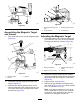
1.Flange(storage
compartment)
4.Flange-headcapscrew
(1/4x1/2inch)
2.Flangelocknut(1/4inch)
5.Manifoldmount
3.Washer(1/4inch)
3.Looselyassemblethemanifoldmounttothe
ange(Figure74)with2ange-headcapscrews
(1/4x1/2inch),2washers(1/4inch),and2
angelocknuts(1/4inch).
4.Looselyassemblethemanifoldmounttothe
dashsupporttube(Figure75)with2U-bolts(3/8
inch)and4angelocknuts(3/8inch).
g299723
Figure75
1.U-bolt(3/8inch)3.Manifoldmount
2.Dashsupporttube
4.Flangelocknut(3/8inch)
5.Tightenthecapscrews,U-bolts,andlocknuts.
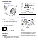
AfxingtheModel/SerialDecal
1.Removethebackingfromthemodel/serial
decal.
2.Afxthedecaltothemanifoldmountasshown
inFigure76.
g303489
Figure76
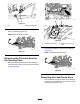
PreparingtheEHISteeringValve
1.Assemble2straighthydraulicttings(-6x12
mm)intotheEHIsteeringvalve(Figure77)as
follows:
•PortLS1
•PortLS2
g299718
Figure77
1.PortLS1(EHIsteering
valve)
3.PortLS2
2.Straighthydraulictting
(-6x12mm)
2.Removethe2plugsfromportPandportTof
theEHIsteeringvalve(Figure78).
27