
Service Manual


Multi Pro 5800 Page 8 − 35 GeoLink Spray System
Pumps
Refer to the Electrical Schematics and Wire Harness
Drawings and Diagrams in Appendix A − Foldout Draw-
ings in this manual for additional information.
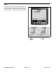
The following inputs can be checked from the Pumps
Screen:
M. SWITCH: ON while the master boom switch is de-
pressed.
NOTE: The Master Boom Switch is a momen-
tary switch that switches the master boom control
ON/OFF. ON will only be displayed on this screen
while the switch is depressed. Therefore, the
master boom control may be active (master
boom icon visible on the Operator’s Information
Screen) while OFF appears on this screen.
RINSE: ON when the optional clean tank rinse kit
rinse pump switch is held in the MOMENTARY
(down) position.
RINSE TIMMED: ON for a 60 second timed period
when the optional clean tank rinse kit rinse pump
switch is in the ON (up) position.
AGITATION VALVE: ON when the agitation switch is
in the ON position.
PUMP: ON when the spray pump switch is in the ON
position.
NEUTRAL: ON when the traction pedal is in neutral.
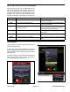
There are no qualifiers involved in the PUMPS function.
When the pump switch input is in the ON position
(PUMP ON), the following output should occur (Fig. 39):
MASTER VALVE ON − TEC output 9: The spray
pump hydraulic proportional control valve PV in the
spray pump control manifold should energize.
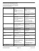
When the optional rinse pump switch input is in the ON
(up) position (RINSE TIMED ON), the following output
should occur (Fig. 40):
RINSE PUMP ON − TEC output 13: For machines
with an optional clean tank rinse kit installed, the
rinse pump relay should energize for 60 seconds.
When the optional rinse pump switch input is held in the
MOMENTARY (down) position (RINSE PUMP ON), the
following output should occur:
RINSE PUMP ON − TEC output 13: For machines
with an optional clean tank rinse kit installed, the
rinse pump relay should energize for as long as the
switch is depressed.
Figure 39 (Spray Pump)
Figure 40 (Optional Rinse Pump)