
Service Manual


Multi Pro 5800Page 7 − 42ExcelaRate Spray System
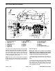
Boom Section Valve Assembly
1. Valve actuator (3)
2. Boom section valve (3)
3. Boom section bypass valve (3)
4. Boom section bypass shut−off valve
5. Pressure transducer
6. Port adapter
7. Clamp (6)
8. Gasket (6)
9. Fork (7)
10. Cap
11. O−ring (11)
12. Adapter
13. Elbow (ported)
14. Elbow
Figure 41
11
11
11
12
13
14
1
1
1
2
2
2
3
3
3
4
5
6
7
7
7
8
8
8
9
9
9
10
The boom section valve assembly includes the right,
center and left boom section valves, a bypass valve for
each of the boom section valves and the boom section
bypass shut−off valve.
IMPORTANT: Each valve actuator has an internal
circuit breaker to protect the actuator motor. The
circuit breaker should reset in 20 seconds after
power to the actuator is removed.
Disassembly (Fig. 41)
1. Remove the boom section valve assembly from ma-
chine (see Spray Control Manifold Assembly in this
chapter).
2. Disassemble boom section valve assembly as need-
ed. Discard any removed O−rings and gaskets.
NOTE: See Boom Section Valve Service and Boom
Section Bypass Valve Service in this chapter for disas-
sembly and assembly information. The valve actuators
are nor serviceable. See Spray System Valve Actuators
in Chapter 6 − Electrical System in this manual for actua-
tor testing information.
Assembly (Fig. 41)
NOTE: Replace, do not reuse gaskets and O−rings.
Coat O−rings and gaskets with vegetable oil or silicone
grease before installation to reduce damage during as-
sembly.
1. Assemble boom section valve assembly.
2. Install boom section valve assembly on machine
(see Spray Control Manifold Assembly in this chapter).