
Service Manual


Multi Pro 5800 Hydraulic SystemPage 5 − 65
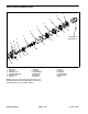
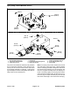
Removal (Fig. 54)
1. Park machine on a level surface, stop engine, en-
gage parking brake and remove key from the ignition
switch.
2. Read the General Precautions for Removing and
Installing Hydraulic System Components at the begin-
ning of the Service and Repairs section of this chapter.
3. Thoroughly clean hydraulic hose ends and fittings at
the pump control manifold.
4. Label all pump control manifold electrical and hy-
draulic connections for assembly purposes.
5. Disconnect wire harness electrical connector from
solenoid valve coil on pump control manifold.
6. Disconnect hydraulic hoses connected to the pump
control manifold. Allow hoses to drain into a suitable
container. Cap or plug openings of control manifold and
hoses to prevent contamination.
7. Loosen, but do not remove, flange nuts (item 2) that
secure spray pump motor to motor mount plate and re-
move guard (item 3).
8. Loosen two (2) set screws (item 7) that secure cou-
pler (item 8) to hydraulic motor shaft. Do not loosen two
(2) set screws that secure coupler to spray pump shaft
so that coupler remains on the pump shaft during motor
removal.
9. Remove the lock nut (item 18) cap screw, flat wash-
ers and springs that secure the motor mount plate
(item 4) to the pump bracket.
10.Support the motor mount plate, control manifold and
motor assembly, slide motor shaft from coupler and re-
move hydraulic motor from machine.
11. Locate and remove woodruff key (item 6) from motor
shaft.
12.Remove two (2) flange head screws and flange nuts
that secure hydraulic motor to motor mount plate. Re-
move motor mount plate from control manifold and mo-
tor assembly.
13.Remove four (4) cap screws and flat washers that se-
cure control manifold to motor and separate control
manifold from motor. Locate and discard two (2) O−rings
(item 29) from motor ports.
14.Remove set screws (item 7) that were loosened in
coupler. Clean threads of set screws and coupler.
Installation (Fig. 54)
1. Secure control manifold to motor:
A. Lubricate two (2) new O−rings and place O−rings
(item 29) in motor ports.
B. Position control manifold to motor making sure
that O−rings remain in position.
C. Install and tighten four (4) cap screws and flat
washers to secure assembly. Tighten cap screws in
a crossing pattern from 15 to 19 ft−lb (20 to 26
N−m).
2. Position motor mount plate to motor and install two
(2) flange head screws and flange nuts to motor and mo-
tor mounting bracket. Leave fasteners loose.
3. Apply antiseize lubricant to motor shaft. Install wood-
ruff key in shaft.
4. Position mount plate, control manifold and motor as-
sembly to machine and slide motor shaft into coupler on
spray pump shaft.
5. Secure motor mount plate to pump bracket with cap
screw (item 14), flat washers, compression springs and
lock nut. Adjust spring tension to 2.12 to 2.25 in. (3.2 to
6.3 mm) as shown.
6. Apply Loctite #242 (or equivalent) to threads of set
screws (item 7) and install set screws into coupler. Fit
motor squarely against motor mount plate and tighten
set screws from 130 to 150 in−lbs (14 to 17 N−m).
7. Position guard (item 3) to motor mount plate making
sure that guard fits around screws used to attach motor
to mount plate. Tighten flange head screws and flange
nuts to secure assembly.
8. Using labels placed during removal, lubricate new
O−rings and install hydraulic hoses to correct hydraulic
fittings on control manifold (see Hydraulic Hose and
Tube Installation in the General Information section of
this chapter).
9. Connect wire harness electrical connector to sole-
noid valve coil on pump control manifold.
10.Charge the hydraulic system (see Charge Hydraulic
System in this chapter).
11. Operate machine and inspect for leaks.