
Service Manual


Multi Pro 5800−D Page 3 − 17 Kubota Diesel Engine
CAUTION
Make sure that hoist or lift used to remove en-
gine can properly support engine. Engine as-
sembly weighs approximately 275 pounds
(125 kg).
IMPORTANT: Make sure to not damage the engine,
fuel hoses, hydraulic lines, electrical harness or
other parts while removing the engine assembly.
22.Using a hoist and the lifting lugs provided on the en-
gine, carefully lift the engine from the machine.
23.If necessary, remove engine brackets, pump
adapter and flywheel coupler from the engine, or engine
mounts from frame.
Installation (Fig. 8)
1. Park machine on a level surface and engage parking
brake.
2. Make sure that all parts removed from the engine
during maintenance or rebuilding (including engine
mount brackets) are reinstalled to the engine assembly.
3. If engine mounts were removed from frame, secure
mounts to frame with cap screws and flange nuts.
IMPORTANT: Make sure to not damage the engine,
fuel hoses, hydraulic lines, electrical harness or
other parts while installing the engine assembly.
CAUTION
Make sure that hoist or lift used to remove en-
gine can properly support engine. Engine as-
sembly weighs approximately 275 pounds
(125 kg).
4. Using a hoist and the lifting lugs provided on the en-
gine, carefully lift the engine into the machine. Insert cap
screws through engine brackets and motor mounts from
above. Install snubbing washers and flange nuts on cap
screws and tighten (Fig. 8).
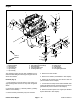
Figure 13
1. Fuel stop solenoid
2. Fuel supply hose
3. Water/fuel filter
4. Throttle cable
5. Cable clamp
6. Cable stop
2
1
3
4
5
6
5. Connect throttle cable to injector pump (Fig. 13):
A. Position throttle cable to engine.
B. Insert the throttle cable end into the swivel in
speed control lever. Slide cable stop onto cable end
and secure with screw.
C. Position throttle cable under cable clamp.
D. Adjust throttle control cable (see Adjust Throttle
Control Cable in the Adjustments section of this
chapter).
6. Connect fuel supply hose to the fuel injector pump
and fuel return hose to fuel rail on engine (Fig. 13). Re-
move clamp from fuel hose that was used to prevent
leakage during engine removal.
7. Using labels placed during engine removal, attach all
engine electrical connections (see step 17. in removal
procedure).
8. Install hydraulic pump assembly to engine (see Pis-
ton (Traction) Pump Installation in Chapter 4 − Hydraulic
System in this manual).
9. Install seat base panels (left side, right side and
front), rear cross member and cross member supports
to machine (Fig. 9).