
Service Manual


Multi Pro 5800 Page 8 − 79 GeoLink Spray System
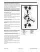
Removal (Fig. 97)
IMPORTANT: Make sure to remove and neutralize
chemicals from spray components before disas-
sembly. Wear protective clothing, chemical resist-
ant gloves and eye protection during repair.
1. Park machine on a level surface, stop engine, en-
gage parking brake and remove key from the ignition
switch.
2. Label wire harness connectors for proper installation
after repairs are completed (agitation valve, ten (10)
nozzle valves, flow meter sensor, pressure transducer).
Disconnect wire harness connectors from spray control
manifold as needed.
3. Label hoses for proper installation after repairs are
completed. Loosen hose clamps and remove forks to
disconnect hoses from spray control manifold as need-
ed.
4. To remove agitation valve assembly:
A. Disconnect clamp securing the left side of flow
meter to adapter.
B. Remove bowl and screen from high pressure fil-
ter if necessary to access valve assembly mounting
fasteners (item 16).
C. Remove fasteners that secure high pressure filter
to mount bracket. Retrieve spacers/washers be-
tween filter and mount bracket.
D. Remove fasteners that secure agitation valve as-
sembly to mount bracket and remove agitation valve
assembly from machine. Discard any removed O−
rings and gaskets.
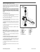
5. The nozzle valve assembly is split by a tee fitting be-
tween nozzle valve 5 and 6, and nozzle valve 7 and 8.
To remove the nozzle valve assembly:
A. Disconnect clamp securing one half of the nozzle
valve assembly to the tee fitting.
B. Remove fasteners that secure the nozzle valve
assembly half being removed to the valve mount and
remove the assembly from the machine. Discard any
removed O−rings and gaskets.
6. See Agitation Valve Assembly and Nozzle Valve As-
sembly in this chapter for additional service information.
Installation (Fig. 97)
NOTE: Replace, do not reuse gaskets and O−rings.
Coat O−rings and gaskets with vegetable oil or silicone
grease before installation to reduce damage during as-
sembly.
1. Fit screw clamp and a new gasket to flanges of
adapter or tee fitting. Tighten screw clamp to secure as-
sembly.
2. Secure assembly to mount bracket with fasteners
and spacers/washers previously removed.
3. Using labels placed during removal to install hoses
to spray control manifold.
4. If removed, install screen and bowl to high pressure
filter.
5. Using labels placed during removal to install wire
harness connectors to spray control manifold.
6. Operate spray system and check for leaks. Repair all
leaks before returning the sprayer to service.