
Service Manual

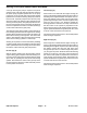


Table Of Contents
- Title Page
- Revision History
- Reader Comments
- Preface
- Table Of Contents
- 1 - Safety
- 2 - Product Records and Maintenance
- 3 - Kubota Diesel Engine
- 4 - Kubota Gasoline Engine
- 5 - Hydraulic System
- Specifications
- General Information
- Hydraulic Schematics
- Hydraulic Flow Circuits
- Special Tools
- Troubleshooting
- Testing
- Traction Circuit - Charge Pressure Test
- Traction Circuit - Charge Pump Flow Test
- Traction Circuit - Wheel Motor Efficiency Test
- Traction Circuit - Traction (Piston) Pump Flow and Relief Pressure Test
- Steering/Boom Lift Circuit - Gear Pump P2 Flow and Circuit Relief Pressure Test (Using Tester with Flow Meter and Pressure...
- Steering/Boom Lift Circuit - Steering Control Valve and Steering Cylinder Test
- Steering/Boom Lift Circuit - Boom Lift Cylinder Internal Leakage Test
- Spray Pump Circuit - Gear Pump P1 Flow Test (Using Tester with Flow Meter and Pressure Gauge)
- Adjustments
- Service and Repairs
- General Precautions for Removing and Installing Hydraulic System Components
- Check Hydraulic Lines and Hoses
- Gear Pump
- Gear Pump Service
- Traction (Piston) Pump
- Traction (Piston) Pump Service
- Wheel Motors
- Wheel Motor Service
- Spray Pump Drive Motor and Control Manifold Assembly
- Spray Pump Drive Motor Service
- Spray Pump Control Manifold Service
- Steering Control Valve
- Steering Control Valve Service
- Steering Cylinder
- Steering Cylinder Service
- Boom Lift Manifold
- Boom Lift Manifold Service
- Boom Lift Cylinders
- Boom Lift Cylinder Service
- Oil Cooler
- Hydraulic Reservoir
- Electrohydraulic In-line (EHi) Steering Valve (Optional AutoSteer Kit)
- Electrohydraulic In-line (EHI) Steering Valve Service (Optional AutoSteer Kit)
- 6 - Electrical System
- General Information
- Electrical Drawings
- Special Tools
- InfoCenter Display
- Troubleshooting
- Electrical System Quick Checks
- Adjustments
- Component Testing
- Fusible Links
- Fuses
- Engine Fuses (Gasoline Engines Only)
- Toro Electronic Controller (TEC)
- PVED-CLS Controller (Optional AutoSteer)
- Ignition Switch
- Indicator Lights (Diesel Engines Only)
- Headlight Switch (Standard)
- Spray-Mode Switch (ExcelaRate Spray Systems Only)
- Application-Rate Switch (machines without GeoLink Spray System)
- Road Switch (Optional AutoSteer)
- Speed-Lock Switch
- Boom Lift Switches
- Spray Pump Enable and Agitation Switches
- Master Boom (Spray Enable) Switch
- Remote Engage Switch (Optional AutoSteer)
- Boom Control Switches
- Speed Lock Coil
- Brake Pedal Switch
- Relays with Four (4) Terminals
- Relays with Five (5) Terminals
- Engine Relays (Gasoline Engines Only)
- Traction Speed Sensor
- Hydraulic Valve Solenoid Coils
- Neutral Switch
- Fuel Run/Stop Solenoid (Diesel Engines Only)
- Glow Plug Controller (Diesel Engines Only)
- Fuel Pump (Gasoline Engines Only)
- Fuel Pump (Diesel Engines Only)
- Fuel Level Sender (Gasoline Engines Only)
- Fuel Level Sender (Diesel Engines Only)
- Coolant Temperature Sender
- Oil Pressure Switch
- CAN-bus Terminator Resistors
- Diode Assemblies
- Resistor Assemblies
- Spray System Valve Actuators
- Operator Seat Switch
- Audible Alarm
- Throttle Assembly (Gasoline Engines Only)
- Flow Meter Sensor
- Pressure Transducer
- Horn Button (Optional)
- Tank Clean Rinse Pump Switch (Optional)
- Foam Marker ON/OFF Switch (Optional)
- Foam Marker Control Switch (Optional)
- Electric Hose Reel Motor Switch (Optional)
- Electric Hose Reel Rate Switch (Optional)
- Road Headlight Switch (Optional)
- Hazard Light Switch (Optional)
- Service and Repairs
- 7 - ExcelaRate Spray System
- Specifications
- General Information
- Special Tools
- ExcelaRate Spray System Diagram
- ExcelaRate Spray System Operation
- InfoCenter Display
- Troubleshooting
- Service and Repairs
- Spray System Components
- Spray Pump
- Spray Pump Service
- Pressure Relief Valve
- Spray Control Manifold Assembly
- Agitation Valve Assembly
- Boom Section Valve Assembly
- Boom Section Valve and Agitation Valve Service
- Agitation Bypass Valve Service
- Boom Section Bypass Valve Service
- Boom Section Bypass Shut-Off Valve and Agitation Throttle Valve Service
- Flow Meter
- Flow Meter Service
- Suction Line
- Agitation Line
- Drain Line
- Turret Bodies
- Turret Body Service
- Nozzle Flow Meter (Optional NozzAlert Nozzle Sensing System)
- Spray Boom Hinge
- Spray Tank
- 8 - GeoLink Spray System
- Calibrating the AutoSteer Steering System Components (Optional) 56
- Specifications
- General Information
- Special Tools
- GeoLink Spray System Diagram
- GeoLink Spray System Operation
- X25 and X30 Control Console Screens
- InfoCenter Display
- Troubleshooting
- Automatic Section Control Override
- Remote Assistance (X30 Consoles Only)
- X25 or X30 Control Console Error Messages
- Crash Reports
- Guidance and Rate Management System
- Operator Advisories (InfoCenter Display)
- Using the InfoCenter Display for Troubleshooting
- Machine Faults (InfoCenter Display)
- AutoSteer Faults (Optional AutoSteer Only)
- Product Handling System
- Adjustments
- Service and Repairs
- GPS Antenna (AGI-4)
- Modem (machines with RTK correction)
- Inertial Measurement Unit (IMU) (machines with RTK correction)
- Automatic Section Controller (ASC-10)
- X25 or X30 Control Console
- CAN-bus Terminator Resistors
- Fuses
- Material Handling “Wet” Components
- Spray Pump
- Spray Pump Service
- Pressure Relief Valve
- Spray Control Manifold Assembly
- Agitation Valve Assembly
- Nozzle Valve Assembly
- Nozzle Valve and Agitation Valve Service
- Agitation Bypass Valve Service
- Agitation Throttle Valve Service
- Flow Meter
- Flow Meter Service
- Suction Line
- Agitation Line
- Drain Line
- Turret Bodies
- Turret Body Service
- Nozzle Flow Meter (Optional NozzAlert Nozzle Sensing System)
- Spray Boom Hinge
- Spray Tank
- 9 - Chassis
- 10 - Ultra Sonic Boom Kit (Optional)
- Appendix A: Foldout Drawings
- Electrical Drawing Designations
- Hydraulic Schematic – Multi Pro 5800 (serial numbers 316000000 to 400699413)
- Hydraulic Schematic – Multi Pro 5800 (serial numbers 400966414 to 405699999)
- Hydraulic Schematic – Multi Pro 5800 (serial numbers above 405700000)
- Hydraulic Schematic – Multi Pro 5800 (serial numbers above 405700000) with AutoSteer (Optional)
- Electrical Schematic – Multi Pro 5800-D (serial numbers 316000000 to 403460000)
- Electrical Schematic – Multi Pro 5800-D (serial numbers 316000000 to 403460000)
- Electrical Schematic – Multi Pro 5800-D (serial numbers above 40346000)
- Electrical Schematic – Multi Pro 5800-D (serial numbers above 40346000)
- Electrical Schematic – Multi Pro 5800-G (serial numbers 316000000 to 403460000)
- Electrical Schematic – Multi Pro 5800-G (serial numbers 316000000 to 403460000)
- Electrical Schematic – Multi Pro 5800-G (serial numbers above 40346000)
- Electrical Schematic – Multi Pro 5800-G (serial numbers above 40346000)
- Electrical Schematic – Multi Pro 5800 (serial numbers above 316000000) with GeoLink Spray System (Optional)
- Electrical Schematic – Ultra Sonic Boom Kit (Optional)
- Front Wire Harness Drawing – Multi Pro 5800-D (serial numbers 316000000 to 403460000)
- Front Wire Harness Diagram – Multi Pro 5800-D (serial numbers 316000000 to 403460000)
- Front Wire Harness Diagram – Multi Pro 5800-D (serial numbers 316000000 to 403460000)
- Front Wire Harness Drawing – Multi Pro 5800-D (serial numbers above 403460000)
- Front Wire Harness Diagram – Multi Pro 5800-D (serial numbers above 403460000)
- Front Wire Harness Diagram – Multi Pro 5800-D (serial numbers above 403460000)
- Front Wire Harness Drawing – Multi Pro 5800-G (serial numbers 316000000 to 403445000)
- Front Wire Harness Diagram – Multi Pro 5800-G (serial numbers 316000000 to 403445000)
- Front Wire Harness Diagram – Multi Pro 5800-G (serial numbers 316000000 to 403445000)
- Front Wire Harness Drawing – Multi Pro 5800-G (serial numbers above 403445000)
- Front Wire Harness Diagram – Multi Pro 5800-G (serial numbers above 403445000)
- Front Wire Harness Diagram – Multi Pro 5800-G (serial numbers above 403445000)
- Rear Wire Harness Drawing – Multi Pro 5800 (serial numbers above 316000000)
- Rear Wire Harness Diagram – Multi Pro 5800 (serial numbers above 316000000)
- Rear Wire Harness Drawing – Multi Pro 5800 (serial numbers above 316000000) with GeoLink Spray System (Optional)
- Rear Wire Harness Diagram – Multi Pro 5800 (serial numbers above 316000000) with GeoLink Spray System (Optional)
- Wire Harness Drawing – AutoSteer Kit (Optional)
- Wire Harness Diagram – AutoSteer Kit (Optional)
- Wire Harness Drawing – Ultra Sonic Boom Kit (Optional)
- Wire Harness Diagram – Ultra Sonic Boom Kit (Optional)
- Main Wire Harness – NozzAlert Nozzle Sensing System (Optional)
- Center Section Wire Harness – NozzAlert Nozzle Sensing System (Optional)
- Right Boom Wire Harness – NozzAlert Nozzle Sensing System (Optional)
- Left Boom Wire Harness – NozzAlert Nozzle Sensing System (Optional)

Multi Pro 5800Hydraulic System Page 5 − 16
Spray Boom Lift Circuit
A two (2) section gear pump is coupled to the piston
(traction) pump. The front gear pump section (closest to
the piston pump) supplies hydraulic flow to the spray
pump drive circuit. The rear gear pump section supplies
hydraulic flow to both the steering and spray boom lift/
lower circuits. Hydraulic pump flow from the rear pump
section is routed to the steering control valve first so the
steering circuit has priority. The gear pump takes its suc-
tion from the hydraulic reservoir. Steering and boom lift/
lower circuit pressure is limited to 1015 PSI (69 bar) by
a relief valve located in the gear pump.
Spray boom lift circuit hydraulic flow can be monitored
at the outlet of the rear gear pump section. Circuit pres-
sure can be measured at a diagnostic fitting in port G on
the boom lift control manifold.
The boom lift control manifold includes three (3) electri-
cally operated valves. Solenoid valve (S1) is used to di-
rect oil flow toward the boom lift cylinders when
energized or allow circuit flow to bypass the cylinders
when de−energized. Solenoid valve (S2) controls hy-
draulic flow to raise or lower the left side boom lift cylin-
der. Solenoid valve (S3) controls hydraulic flow to raise
or lower the right side boom lift cylinder. Solenoid valves
S1 and S2 each have 2 coils (upper and lower).
While operating the machine during conditions of not
raising or lowering a spray boom (boom lift switches in
the neutral (center) position), all of the boom lift control
manifold valves (S1, S2 and S3) are de−energized. The
de−energized valve (S1) allows hydraulic flow to return
to tank through the boom lift control manifold. Flow re-
turns to the oil filter and then to the hydraulic reservoir.
Raise Spray Boom (Fig. 12)
When a boom lift switch is depressed to the raise posi-
tion, manifold solenoid valves (S1) and the upper coil for
either solenoid valve (S2) (LH cylinder) or (S3) (RH cyl-
inder) are energized. The energized (S1) directs oil flow
toward the manifold solenoid valves. The energized up-
per coil of solenoid valve (S2 or S3) shifts the valve to
allow pump flow to be directed toward the rod end of the
lift cylinder through a manifold check valve and orifice
that controls lift speed. The lift cylinder retracts to raise
the boom section.
Displaced oil from the barrel end of the lift cylinder re-
turns to the manifold, bypasses an orifice, is routed
through the shifted valve (S2 or S3), exits the control
manifold through port T, is routed to the oil filter and then
returns to the hydraulic reservoir.
When the lift switch is returned to the neutral (center)
position, the manifold solenoid valves are de−ener-
gized. The de−energized valve (S1) allows hydraulic
flow to return to tank through the manifold. The boom lift
cylinder is held in the raised position by de−energized
valve (S2) (LH cylinder) or (S3) (RH cylinder).
Lower Spray Boom (Fig. 12)
When a boom lift switch is depressed to the lower posi-
tion, manifold solenoid valves (S1) and the lower coil for
either solenoid valve (S2) (LH cylinder) or (S3) (RH cyl-
inder) are energized. The energized (S1) directs oil flow
toward the manifold solenoid valves. The energized
lower coil of solenoid valve (S2 or S3) shifts the valve to
allow pump flow to be directed toward the barrel end of
the lift cylinder through an orifice that controls lowering
speed. The lift cylinder extends to lower the boom sec-
tion.
As circuit pressure increases, a manifold sensing line
shifts the pilot operated check valve (PC1 for the LH cyl-
inder or PC2 for the RH cylinder) to allow a return path
for oil from the rod end of the lift cylinder. Displaced oil
from the rod end of the lift cylinder returns to the man-
ifold, bypasses an orifice, flows through the shifted
check valve, is routed through the shifted valve (S2 or
S3), exits the control manifold through port T, is routed
to the oil filter and then returns to the hydraulic reservoir.
When the lift switch is returned to the neutral (center)
position, the manifold solenoid valves are both de−ener-
gized. The de−
energized valve (S1) allows hydraulic
flow to return to tank through the manifold. The boom lift
cylinder is held in the raised position by de−energized
valve (S2) (LH cylinder) or (S3) (RH cylinder).