
Service Manual


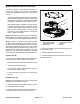


Table Of Contents
- Title Page
- Revision History
- Reader Comments
- Preface
- Table Of Contents
- 1 - Safety
- 2 - Product Records and Maintenance
- 3 - Kubota Diesel Engine
- 4 - Kubota Gasoline Engine
- 5 - Hydraulic System
- Specifications
- General Information
- Hydraulic Schematics
- Hydraulic Flow Circuits
- Special Tools
- Troubleshooting
- Testing
- Traction Circuit - Charge Pressure Test
- Traction Circuit - Charge Pump Flow Test
- Traction Circuit - Wheel Motor Efficiency Test
- Traction Circuit - Traction (Piston) Pump Flow and Relief Pressure Test
- Steering/Boom Lift Circuit - Gear Pump P2 Flow and Circuit Relief Pressure Test (Using Tester with Flow Meter and Pressure...
- Steering/Boom Lift Circuit - Steering Control Valve and Steering Cylinder Test
- Steering/Boom Lift Circuit - Boom Lift Cylinder Internal Leakage Test
- Spray Pump Circuit - Gear Pump P1 Flow Test (Using Tester with Flow Meter and Pressure Gauge)
- Adjustments
- Service and Repairs
- General Precautions for Removing and Installing Hydraulic System Components
- Check Hydraulic Lines and Hoses
- Gear Pump
- Gear Pump Service
- Traction (Piston) Pump
- Traction (Piston) Pump Service
- Wheel Motors
- Wheel Motor Service
- Spray Pump Drive Motor and Control Manifold Assembly
- Spray Pump Drive Motor Service
- Spray Pump Control Manifold Service
- Steering Control Valve
- Steering Control Valve Service
- Steering Cylinder
- Steering Cylinder Service
- Boom Lift Manifold
- Boom Lift Manifold Service
- Boom Lift Cylinders
- Boom Lift Cylinder Service
- Oil Cooler
- Hydraulic Reservoir
- Electrohydraulic In-line (EHi) Steering Valve (Optional AutoSteer Kit)
- Electrohydraulic In-line (EHI) Steering Valve Service (Optional AutoSteer Kit)
- 6 - Electrical System
- General Information
- Electrical Drawings
- Special Tools
- InfoCenter Display
- Troubleshooting
- Electrical System Quick Checks
- Adjustments
- Component Testing
- Fusible Links
- Fuses
- Engine Fuses (Gasoline Engines Only)
- Toro Electronic Controller (TEC)
- PVED-CLS Controller (Optional AutoSteer)
- Ignition Switch
- Indicator Lights (Diesel Engines Only)
- Headlight Switch (Standard)
- Spray-Mode Switch (ExcelaRate Spray Systems Only)
- Application-Rate Switch (machines without GeoLink Spray System)
- Road Switch (Optional AutoSteer)
- Speed-Lock Switch
- Boom Lift Switches
- Spray Pump Enable and Agitation Switches
- Master Boom (Spray Enable) Switch
- Remote Engage Switch (Optional AutoSteer)
- Boom Control Switches
- Speed Lock Coil
- Brake Pedal Switch
- Relays with Four (4) Terminals
- Relays with Five (5) Terminals
- Engine Relays (Gasoline Engines Only)
- Traction Speed Sensor
- Hydraulic Valve Solenoid Coils
- Neutral Switch
- Fuel Run/Stop Solenoid (Diesel Engines Only)
- Glow Plug Controller (Diesel Engines Only)
- Fuel Pump (Gasoline Engines Only)
- Fuel Pump (Diesel Engines Only)
- Fuel Level Sender (Gasoline Engines Only)
- Fuel Level Sender (Diesel Engines Only)
- Coolant Temperature Sender
- Oil Pressure Switch
- CAN-bus Terminator Resistors
- Diode Assemblies
- Resistor Assemblies
- Spray System Valve Actuators
- Operator Seat Switch
- Audible Alarm
- Throttle Assembly (Gasoline Engines Only)
- Flow Meter Sensor
- Pressure Transducer
- Horn Button (Optional)
- Tank Clean Rinse Pump Switch (Optional)
- Foam Marker ON/OFF Switch (Optional)
- Foam Marker Control Switch (Optional)
- Electric Hose Reel Motor Switch (Optional)
- Electric Hose Reel Rate Switch (Optional)
- Road Headlight Switch (Optional)
- Hazard Light Switch (Optional)
- Service and Repairs
- 7 - ExcelaRate Spray System
- Specifications
- General Information
- Special Tools
- ExcelaRate Spray System Diagram
- ExcelaRate Spray System Operation
- InfoCenter Display
- Troubleshooting
- Service and Repairs
- Spray System Components
- Spray Pump
- Spray Pump Service
- Pressure Relief Valve
- Spray Control Manifold Assembly
- Agitation Valve Assembly
- Boom Section Valve Assembly
- Boom Section Valve and Agitation Valve Service
- Agitation Bypass Valve Service
- Boom Section Bypass Valve Service
- Boom Section Bypass Shut-Off Valve and Agitation Throttle Valve Service
- Flow Meter
- Flow Meter Service
- Suction Line
- Agitation Line
- Drain Line
- Turret Bodies
- Turret Body Service
- Nozzle Flow Meter (Optional NozzAlert Nozzle Sensing System)
- Spray Boom Hinge
- Spray Tank
- 8 - GeoLink Spray System
- Calibrating the AutoSteer Steering System Components (Optional) 56
- Specifications
- General Information
- Special Tools
- GeoLink Spray System Diagram
- GeoLink Spray System Operation
- X25 and X30 Control Console Screens
- InfoCenter Display
- Troubleshooting
- Automatic Section Control Override
- Remote Assistance (X30 Consoles Only)
- X25 or X30 Control Console Error Messages
- Crash Reports
- Guidance and Rate Management System
- Operator Advisories (InfoCenter Display)
- Using the InfoCenter Display for Troubleshooting
- Machine Faults (InfoCenter Display)
- AutoSteer Faults (Optional AutoSteer Only)
- Product Handling System
- Adjustments
- Service and Repairs
- GPS Antenna (AGI-4)
- Modem (machines with RTK correction)
- Inertial Measurement Unit (IMU) (machines with RTK correction)
- Automatic Section Controller (ASC-10)
- X25 or X30 Control Console
- CAN-bus Terminator Resistors
- Fuses
- Material Handling “Wet” Components
- Spray Pump
- Spray Pump Service
- Pressure Relief Valve
- Spray Control Manifold Assembly
- Agitation Valve Assembly
- Nozzle Valve Assembly
- Nozzle Valve and Agitation Valve Service
- Agitation Bypass Valve Service
- Agitation Throttle Valve Service
- Flow Meter
- Flow Meter Service
- Suction Line
- Agitation Line
- Drain Line
- Turret Bodies
- Turret Body Service
- Nozzle Flow Meter (Optional NozzAlert Nozzle Sensing System)
- Spray Boom Hinge
- Spray Tank
- 9 - Chassis
- 10 - Ultra Sonic Boom Kit (Optional)
- Appendix A: Foldout Drawings
- Electrical Drawing Designations
- Hydraulic Schematic – Multi Pro 5800 (serial numbers 316000000 to 400699413)
- Hydraulic Schematic – Multi Pro 5800 (serial numbers 400966414 to 405699999)
- Hydraulic Schematic – Multi Pro 5800 (serial numbers above 405700000)
- Hydraulic Schematic – Multi Pro 5800 (serial numbers above 405700000) with AutoSteer (Optional)
- Electrical Schematic – Multi Pro 5800-D (serial numbers 316000000 to 403460000)
- Electrical Schematic – Multi Pro 5800-D (serial numbers 316000000 to 403460000)
- Electrical Schematic – Multi Pro 5800-D (serial numbers above 40346000)
- Electrical Schematic – Multi Pro 5800-D (serial numbers above 40346000)
- Electrical Schematic – Multi Pro 5800-G (serial numbers 316000000 to 403460000)
- Electrical Schematic – Multi Pro 5800-G (serial numbers 316000000 to 403460000)
- Electrical Schematic – Multi Pro 5800-G (serial numbers above 40346000)
- Electrical Schematic – Multi Pro 5800-G (serial numbers above 40346000)
- Electrical Schematic – Multi Pro 5800 (serial numbers above 316000000) with GeoLink Spray System (Optional)
- Electrical Schematic – Ultra Sonic Boom Kit (Optional)
- Front Wire Harness Drawing – Multi Pro 5800-D (serial numbers 316000000 to 403460000)
- Front Wire Harness Diagram – Multi Pro 5800-D (serial numbers 316000000 to 403460000)
- Front Wire Harness Diagram – Multi Pro 5800-D (serial numbers 316000000 to 403460000)
- Front Wire Harness Drawing – Multi Pro 5800-D (serial numbers above 403460000)
- Front Wire Harness Diagram – Multi Pro 5800-D (serial numbers above 403460000)
- Front Wire Harness Diagram – Multi Pro 5800-D (serial numbers above 403460000)
- Front Wire Harness Drawing – Multi Pro 5800-G (serial numbers 316000000 to 403445000)
- Front Wire Harness Diagram – Multi Pro 5800-G (serial numbers 316000000 to 403445000)
- Front Wire Harness Diagram – Multi Pro 5800-G (serial numbers 316000000 to 403445000)
- Front Wire Harness Drawing – Multi Pro 5800-G (serial numbers above 403445000)
- Front Wire Harness Diagram – Multi Pro 5800-G (serial numbers above 403445000)
- Front Wire Harness Diagram – Multi Pro 5800-G (serial numbers above 403445000)
- Rear Wire Harness Drawing – Multi Pro 5800 (serial numbers above 316000000)
- Rear Wire Harness Diagram – Multi Pro 5800 (serial numbers above 316000000)
- Rear Wire Harness Drawing – Multi Pro 5800 (serial numbers above 316000000) with GeoLink Spray System (Optional)
- Rear Wire Harness Diagram – Multi Pro 5800 (serial numbers above 316000000) with GeoLink Spray System (Optional)
- Wire Harness Drawing – AutoSteer Kit (Optional)
- Wire Harness Diagram – AutoSteer Kit (Optional)
- Wire Harness Drawing – Ultra Sonic Boom Kit (Optional)
- Wire Harness Diagram – Ultra Sonic Boom Kit (Optional)
- Main Wire Harness – NozzAlert Nozzle Sensing System (Optional)
- Center Section Wire Harness – NozzAlert Nozzle Sensing System (Optional)
- Right Boom Wire Harness – NozzAlert Nozzle Sensing System (Optional)
- Left Boom Wire Harness – NozzAlert Nozzle Sensing System (Optional)

Multi Pro 5800Page 8 − 62GeoLink Spray System
Modem (machines with RTK correction)
A modem is required on units with RTK correction to
connect the machine to the Internet. Two different
modems are used based on the type of cellular service
chosen.
CDMA (Code Division Multiple Access): The primary
type cellular technology for cell phones used in the
United States. Cell phone providers that use CDMA
technology include Verison, Sprint, Bell and Telus.
GSM (Global System for Mobile): The primary type
of cellular technology used for cell phones in coun-
tries other than the United States. Within the United
States, a much smaller number of network service
providers are on the GSM standard, among them
AT&T, T−Mobile and Rogers.
NOTE: RTK enhanced systems include a modem and
IMU installed in the GPS antenna housing, plus a short
vertical antenna mounted alongside the GPS antenna.
NOTE: The ASC−10, the X25 or X30 control console,
the GPS antenna assembly (including the modem and
the IMU for machines with RTK correction) are pro-
grammed specifically for each sprayer. If any of these
components require replacement for any reason, con-
tact the National Service Network (NSN) or your Toro
Distributor. The replacement components provided
should arrive pre−programmed for the specific sprayer.
Removal (Fig. 80)
1. Disconnect the cellular antenna from the GPS anten-
na and remove the GPS antenna from the sprayer.
2. Remove the bottom cover from the antenna housing.
3. .If removing an existing modem:
A. Detach the coaxial cellular antenna connector
from the GPS antenna housing.
B. Carefully remove the modem from the antenna
housing.
Installation (Fig. 80)
NOTE: For initial installation, remove the antenna plug
assembly from the antenna housing.
1. Align and install the coaxial cellular antenna connec-
tor to the GPS antenna housing.
2. Align the 10−pin connector and press the modem in-
to the GPS antenna housing until it is fully seated.
1
2
3
4
1. GPS antenna assembly
(shown upside−down)
2. Bottom cover
3. Coaxial cellular antenna
connector
4. Modem
Figure 80
3. Secure the modem to the antenna housing with the
two (2) captive screws.
4. Install the GPS antenna bottom cover.
5. Install the GPS antenna to the sprayer and connect
the cellular antenna.