
Service Manual


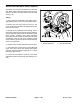
Table Of Contents
- Title Page
- Revision History
- Reader Comments
- Preface
- Table Of Contents
- 1 - Safety
- 2 - Product Records and Maintenance
- 3 - Kubota Diesel Engine
- 4 - Kubota Gasoline Engine
- 5 - Hydraulic System
- Specifications
- General Information
- Hydraulic Schematics
- Hydraulic Flow Circuits
- Special Tools
- Troubleshooting
- Testing
- Traction Circuit - Charge Pressure Test
- Traction Circuit - Charge Pump Flow Test
- Traction Circuit - Wheel Motor Efficiency Test
- Traction Circuit - Traction (Piston) Pump Flow and Relief Pressure Test
- Steering/Boom Lift Circuit - Gear Pump P2 Flow and Circuit Relief Pressure Test (Using Tester with Flow Meter and Pressure...
- Steering/Boom Lift Circuit - Steering Control Valve and Steering Cylinder Test
- Steering/Boom Lift Circuit - Boom Lift Cylinder Internal Leakage Test
- Spray Pump Circuit - Gear Pump P1 Flow Test (Using Tester with Flow Meter and Pressure Gauge)
- Adjustments
- Service and Repairs
- General Precautions for Removing and Installing Hydraulic System Components
- Check Hydraulic Lines and Hoses
- Gear Pump
- Gear Pump Service
- Traction (Piston) Pump
- Traction (Piston) Pump Service
- Wheel Motors
- Wheel Motor Service
- Spray Pump Drive Motor and Control Manifold Assembly
- Spray Pump Drive Motor Service
- Spray Pump Control Manifold Service
- Steering Control Valve
- Steering Control Valve Service
- Steering Cylinder
- Steering Cylinder Service
- Boom Lift Manifold
- Boom Lift Manifold Service
- Boom Lift Cylinders
- Boom Lift Cylinder Service
- Oil Cooler
- Hydraulic Reservoir
- Electrohydraulic In-line (EHi) Steering Valve (Optional AutoSteer Kit)
- Electrohydraulic In-line (EHI) Steering Valve Service (Optional AutoSteer Kit)
- 6 - Electrical System
- General Information
- Electrical Drawings
- Special Tools
- InfoCenter Display
- Troubleshooting
- Electrical System Quick Checks
- Adjustments
- Component Testing
- Fusible Links
- Fuses
- Engine Fuses (Gasoline Engines Only)
- Toro Electronic Controller (TEC)
- PVED-CLS Controller (Optional AutoSteer)
- Ignition Switch
- Indicator Lights (Diesel Engines Only)
- Headlight Switch (Standard)
- Spray-Mode Switch (ExcelaRate Spray Systems Only)
- Application-Rate Switch (machines without GeoLink Spray System)
- Road Switch (Optional AutoSteer)
- Speed-Lock Switch
- Boom Lift Switches
- Spray Pump Enable and Agitation Switches
- Master Boom (Spray Enable) Switch
- Remote Engage Switch (Optional AutoSteer)
- Boom Control Switches
- Speed Lock Coil
- Brake Pedal Switch
- Relays with Four (4) Terminals
- Relays with Five (5) Terminals
- Engine Relays (Gasoline Engines Only)
- Traction Speed Sensor
- Hydraulic Valve Solenoid Coils
- Neutral Switch
- Fuel Run/Stop Solenoid (Diesel Engines Only)
- Glow Plug Controller (Diesel Engines Only)
- Fuel Pump (Gasoline Engines Only)
- Fuel Pump (Diesel Engines Only)
- Fuel Level Sender (Gasoline Engines Only)
- Fuel Level Sender (Diesel Engines Only)
- Coolant Temperature Sender
- Oil Pressure Switch
- CAN-bus Terminator Resistors
- Diode Assemblies
- Resistor Assemblies
- Spray System Valve Actuators
- Operator Seat Switch
- Audible Alarm
- Throttle Assembly (Gasoline Engines Only)
- Flow Meter Sensor
- Pressure Transducer
- Horn Button (Optional)
- Tank Clean Rinse Pump Switch (Optional)
- Foam Marker ON/OFF Switch (Optional)
- Foam Marker Control Switch (Optional)
- Electric Hose Reel Motor Switch (Optional)
- Electric Hose Reel Rate Switch (Optional)
- Road Headlight Switch (Optional)
- Hazard Light Switch (Optional)
- Service and Repairs
- 7 - ExcelaRate Spray System
- Specifications
- General Information
- Special Tools
- ExcelaRate Spray System Diagram
- ExcelaRate Spray System Operation
- InfoCenter Display
- Troubleshooting
- Service and Repairs
- Spray System Components
- Spray Pump
- Spray Pump Service
- Pressure Relief Valve
- Spray Control Manifold Assembly
- Agitation Valve Assembly
- Boom Section Valve Assembly
- Boom Section Valve and Agitation Valve Service
- Agitation Bypass Valve Service
- Boom Section Bypass Valve Service
- Boom Section Bypass Shut-Off Valve and Agitation Throttle Valve Service
- Flow Meter
- Flow Meter Service
- Suction Line
- Agitation Line
- Drain Line
- Turret Bodies
- Turret Body Service
- Nozzle Flow Meter (Optional NozzAlert Nozzle Sensing System)
- Spray Boom Hinge
- Spray Tank
- 8 - GeoLink Spray System
- Calibrating the AutoSteer Steering System Components (Optional) 56
- Specifications
- General Information
- Special Tools
- GeoLink Spray System Diagram
- GeoLink Spray System Operation
- X25 and X30 Control Console Screens
- InfoCenter Display
- Troubleshooting
- Automatic Section Control Override
- Remote Assistance (X30 Consoles Only)
- X25 or X30 Control Console Error Messages
- Crash Reports
- Guidance and Rate Management System
- Operator Advisories (InfoCenter Display)
- Using the InfoCenter Display for Troubleshooting
- Machine Faults (InfoCenter Display)
- AutoSteer Faults (Optional AutoSteer Only)
- Product Handling System
- Adjustments
- Service and Repairs
- GPS Antenna (AGI-4)
- Modem (machines with RTK correction)
- Inertial Measurement Unit (IMU) (machines with RTK correction)
- Automatic Section Controller (ASC-10)
- X25 or X30 Control Console
- CAN-bus Terminator Resistors
- Fuses
- Material Handling “Wet” Components
- Spray Pump
- Spray Pump Service
- Pressure Relief Valve
- Spray Control Manifold Assembly
- Agitation Valve Assembly
- Nozzle Valve Assembly
- Nozzle Valve and Agitation Valve Service
- Agitation Bypass Valve Service
- Agitation Throttle Valve Service
- Flow Meter
- Flow Meter Service
- Suction Line
- Agitation Line
- Drain Line
- Turret Bodies
- Turret Body Service
- Nozzle Flow Meter (Optional NozzAlert Nozzle Sensing System)
- Spray Boom Hinge
- Spray Tank
- 9 - Chassis
- 10 - Ultra Sonic Boom Kit (Optional)
- Appendix A: Foldout Drawings
- Electrical Drawing Designations
- Hydraulic Schematic – Multi Pro 5800 (serial numbers 316000000 to 400699413)
- Hydraulic Schematic – Multi Pro 5800 (serial numbers 400966414 to 405699999)
- Hydraulic Schematic – Multi Pro 5800 (serial numbers above 405700000)
- Hydraulic Schematic – Multi Pro 5800 (serial numbers above 405700000) with AutoSteer (Optional)
- Electrical Schematic – Multi Pro 5800-D (serial numbers 316000000 to 403460000)
- Electrical Schematic – Multi Pro 5800-D (serial numbers 316000000 to 403460000)
- Electrical Schematic – Multi Pro 5800-D (serial numbers above 40346000)
- Electrical Schematic – Multi Pro 5800-D (serial numbers above 40346000)
- Electrical Schematic – Multi Pro 5800-G (serial numbers 316000000 to 403460000)
- Electrical Schematic – Multi Pro 5800-G (serial numbers 316000000 to 403460000)
- Electrical Schematic – Multi Pro 5800-G (serial numbers above 40346000)
- Electrical Schematic – Multi Pro 5800-G (serial numbers above 40346000)
- Electrical Schematic – Multi Pro 5800 (serial numbers above 316000000) with GeoLink Spray System (Optional)
- Electrical Schematic – Ultra Sonic Boom Kit (Optional)
- Front Wire Harness Drawing – Multi Pro 5800-D (serial numbers 316000000 to 403460000)
- Front Wire Harness Diagram – Multi Pro 5800-D (serial numbers 316000000 to 403460000)
- Front Wire Harness Diagram – Multi Pro 5800-D (serial numbers 316000000 to 403460000)
- Front Wire Harness Drawing – Multi Pro 5800-D (serial numbers above 403460000)
- Front Wire Harness Diagram – Multi Pro 5800-D (serial numbers above 403460000)
- Front Wire Harness Diagram – Multi Pro 5800-D (serial numbers above 403460000)
- Front Wire Harness Drawing – Multi Pro 5800-G (serial numbers 316000000 to 403445000)
- Front Wire Harness Diagram – Multi Pro 5800-G (serial numbers 316000000 to 403445000)
- Front Wire Harness Diagram – Multi Pro 5800-G (serial numbers 316000000 to 403445000)
- Front Wire Harness Drawing – Multi Pro 5800-G (serial numbers above 403445000)
- Front Wire Harness Diagram – Multi Pro 5800-G (serial numbers above 403445000)
- Front Wire Harness Diagram – Multi Pro 5800-G (serial numbers above 403445000)
- Rear Wire Harness Drawing – Multi Pro 5800 (serial numbers above 316000000)
- Rear Wire Harness Diagram – Multi Pro 5800 (serial numbers above 316000000)
- Rear Wire Harness Drawing – Multi Pro 5800 (serial numbers above 316000000) with GeoLink Spray System (Optional)
- Rear Wire Harness Diagram – Multi Pro 5800 (serial numbers above 316000000) with GeoLink Spray System (Optional)
- Wire Harness Drawing – AutoSteer Kit (Optional)
- Wire Harness Diagram – AutoSteer Kit (Optional)
- Wire Harness Drawing – Ultra Sonic Boom Kit (Optional)
- Wire Harness Diagram – Ultra Sonic Boom Kit (Optional)
- Main Wire Harness – NozzAlert Nozzle Sensing System (Optional)
- Center Section Wire Harness – NozzAlert Nozzle Sensing System (Optional)
- Right Boom Wire Harness – NozzAlert Nozzle Sensing System (Optional)
- Left Boom Wire Harness – NozzAlert Nozzle Sensing System (Optional)

Multi Pro 5800 Page 6 − 97 Electrical System
Tank Clean Rinse Pump Switch (Optional)
The clean tank rinse kit switch is used to turn the optional
rinse pump ON or OFF. Pressing the upper portion of the
switch energizes the rinse pump for a 60 second timed
period. Pressing the lower portion of the switch ener-
gizes the rinse pump momentarily (pump remains ON
only as long as the switch is pressed). Kits with serial
numbers below 316000000 use an illuminated switch.
The light on the switch will illuminate when the rinse
pump is operating. The Toro Electronic Controller (TEC)
monitors the operation of the rinse kit switch as an input
and provides an output to energize the rinse pump relay.
The rinse kit switch is located on the instrument panel to
the right of the steering column (Fig. 142).
Testing
The clean rinse kit switch and its circuit wiring can be
tested as a TEC input or qualifier using the InfoCenter
Display (see InfoCenter Display − Diagnostics Screen in
this chapter). If testing determines that the switch and
circuit wiring are not functioning correctly, proceed with
the following test procedure:
1. Park machine on a level surface, stop engine and en-
gage parking brake. Remove key from ignition switch.
2. Locate clean rinse kit switch under instrument panel
and unplug machine wire harness connector from
switch.
3. With the use of a multimeter (ohms setting), the clean
rinse kit switch functions may be tested to determine
whether continuity exists between the various terminals
for each switch position. The switch terminals are
marked as shown (Fig. 143) and the circuitry of the
switch is shown in the table (Fig. 144). Verify continuity
between switch terminals.
4. Replace switch if testing determines that it is faulty.
5. If the switch tests correctly and a circuit problem still
exists, check wire harness (see Electrical Schematic
and Wire Harness Drawings in Appendix A − Foldout
Drawings in this manual).
6. Connect the harness connector to the clean rinse kit
switch after testing.
1. Instrument panel 2. Rinse kit switch (opt.)
Figure 142
1
2
Figure 143
BACK OF SWITCH
SWITCH
POSITION
CLOSED
TERMINALS
OPEN
TERMINALS
ON 2 + 1, 5 + 4 2 + 3, 5 + 6
OFF NONE ALL
MOMENTARY 2 + 3, 5 + 6 2 + 1, 5 + 4
Figure 144
NOTE: Clean tank rinse kit switch terminals 4, 5 and 6
are not used on Multi Pro 5800 machines.