
Service Manual


Multi Pro 5800Hydraulic System Page 5 − 16
Spray Boom Lift Circuit
A two (2) section gear pump is coupled to the piston
(traction) pump. The front gear pump section (closest to
the piston pump) supplies hydraulic flow to the spray
pump drive circuit. The rear gear pump section supplies
hydraulic flow to both the steering and spray boom lift/
lower circuits. Hydraulic pump flow from the rear pump
section is routed to the steering control valve first so the
steering circuit has priority. The gear pump takes its suc-
tion from the hydraulic reservoir. Steering and boom lift/
lower circuit pressure is limited to 1015 PSI (69 bar) by
a relief valve located in the gear pump.
Spray boom lift circuit hydraulic flow can be monitored
at the outlet of the rear gear pump section. Circuit pres-
sure can be measured at a diagnostic fitting in port G on
the boom lift control manifold.
The boom lift control manifold includes three (3) electri-
cally operated valves. Solenoid valve (S1) is used to di-
rect oil flow toward the boom lift cylinders when
energized or allow circuit flow to bypass the cylinders
when de−energized. Solenoid valve (S2) controls hy-
draulic flow to raise or lower the left side boom lift cylin-
der. Solenoid valve (S3) controls hydraulic flow to raise
or lower the right side boom lift cylinder. Solenoid valves
S1 and S2 each have 2 coils (upper and lower).
While operating the machine during conditions of not
raising or lowering a spray boom (boom lift switches in
the neutral (center) position), all of the boom lift control
manifold valves (S1, S2 and S3) are de−energized. The
de−energized valve (S1) allows hydraulic flow to return
to tank through the boom lift control manifold. Flow re-
turns to the oil filter and then to the hydraulic reservoir.
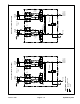
Raise Spray Boom (Fig. 12)
When a boom lift switch is depressed to the raise posi-
tion, manifold solenoid valves (S1) and the upper coil for
either solenoid valve (S2) (LH cylinder) or (S3) (RH cyl-
inder) are energized. The energized (S1) directs oil flow
toward the manifold solenoid valves. The energized up-
per coil of solenoid valve (S2 or S3) shifts the valve to
allow pump flow to be directed toward the rod end of the
lift cylinder through a manifold check valve and orifice
that controls lift speed. The lift cylinder retracts to raise
the boom section.
Displaced oil from the barrel end of the lift cylinder re-
turns to the manifold, bypasses an orifice, is routed
through the shifted valve (S2 or S3), exits the control
manifold through port T, is routed to the oil filter and then
returns to the hydraulic reservoir.
When the lift switch is returned to the neutral (center)
position, the manifold solenoid valves are de−ener-
gized. The de−energized valve (S1) allows hydraulic
flow to return to tank through the manifold. The boom lift
cylinder is held in the raised position by de−energized
valve (S2) (LH cylinder) or (S3) (RH cylinder).
Lower Spray Boom (Fig. 12)
When a boom lift switch is depressed to the lower posi-
tion, manifold solenoid valves (S1) and the lower coil for
either solenoid valve (S2) (LH cylinder) or (S3) (RH cyl-
inder) are energized. The energized (S1) directs oil flow
toward the manifold solenoid valves. The energized
lower coil of solenoid valve (S2 or S3) shifts the valve to
allow pump flow to be directed toward the barrel end of
the lift cylinder through an orifice that controls lowering
speed. The lift cylinder extends to lower the boom sec-
tion.
As circuit pressure increases, a manifold sensing line
shifts the pilot operated check valve (PC1 for the LH cyl-
inder or PC2 for the RH cylinder) to allow a return path
for oil from the rod end of the lift cylinder. Displaced oil
from the rod end of the lift cylinder returns to the man-
ifold, bypasses an orifice, flows through the shifted
check valve, is routed through the shifted valve (S2 or
S3), exits the control manifold through port T, is routed
to the oil filter and then returns to the hydraulic reservoir.
When the lift switch is returned to the neutral (center)
position, the manifold solenoid valves are both de−ener-
gized. The de−
energized valve (S1) allows hydraulic
flow to return to tank through the manifold. The boom lift
cylinder is held in the raised position by de−energized
valve (S2) (LH cylinder) or (S3) (RH cylinder).