
Service Manual


Multi Pro 5800Page 8 − 58GeoLink Spray System
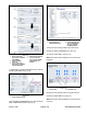
Figure 67
8. Remove the cap from the 3−socket connector of the
kit wire harness CAN port labeled DUPLICATE DIAG
CONNECTOR, and plug the 3−pin connector USB/CAN
interface cable into the 3−socket connector (Fig. 68).
12
3
1. 3−socket connector
(labeled DUPLICATE
DIAG CONNECTOR—
AutoSteer wire harness)
2. 3−pin connector
(USB/CAN interface
cable)
3. Cap
Figure 68
1
2
3
1. Transport position
2. Enable position
3. Enable/Transport switch
Figure 69
9. On the dash panel of the machine, press the enable/
transport switch to the ENABLE position (Fig. 69).
10.On your laptop computer, click the PVED−
CLS_2.00_REV_D.P1D file.
11. In the System Navigator tab, navigate the AUTO
CALIBRATION directory, and click the + icon (Fig. 70).
12.Start the engine of the machine.
13.Turn the steering wheel as needed to position the
front tires straight ahead.
14.Click the SPOOL CALIBRATION icon (Fig. 70).
15.On the spool calibration page, click the GOTO
SPOOL CALIBRATION MODE icon (Fig. 70).
1. GOTO SPOOL CALI−
BRATION MODE icon
2. System Navigator tab,
AUTO CALIBRATION
directory, and SPOOL
CALIBRATION icon
Figure 70
16.Click the START CALIBRATION icon (Fig. 71).
NOTE: The service mode state must display Spool Cali-
bration Armed before starting calibration.
IMPORTANT: DO NOT touch the steering wheel.
The steering wheel moves while spool calibrations pro-
ceeds. The spool calibration process takes several min-
utes. Note that the wheel movement status changes in
Status tab. Calibration is finished when Service Mode
State field displays SPOOL PARAMETERS READY TO
UPDATE.