
Service Manual


Multi Pro 5800 Page 6 − 87 Electrical System
CAN−bus Terminator Resistors
System communication between the Toro Electronic
Controller (TEC), the InfoCenter display, and in the case
of gasoline engine powered machines, the Kubota En-
gine Controller is accomplished on a CAN−bus commu-
nication system. Two (2) specially designed, twisted
cables form the bus for the network used on the ma-
chine. These wires provide the data pathways between
machine components. At the ends of the twisted pair of
bus cables are two (2) 120 ohm terminator resistors.
The CAN−bus terminator resistors plug into the wire
harness in the control console. One of the terminator
resistors is under the switch panel on the control console
and the second resistor is located near the TEC and fuse
block. The wire harness connectors have a blue insert
to identify the proper location for the termination resist-
ors.
For machines with GeoLink spray systems, the AGI−4
antenna, X25 or X30 control console and ASC−10 auto
section controller communicate with each other on a
separate CAN−bus network. At the ends of the twisted
pair of bus cables are two (2) additional 120 ohm termi-
nator resistors. The GeoLink Can−bus network is not
connected to the sprayer traction unit CAN−bus.
For machines with GeoLink spray systems, one of the
terminator resistors is under the operator seat and the
second resistor is located near the ASC−10 at the rear
of the machine. The wire harness connectors have a
blue insert to identify the proper location for the termina-
tion resistors.
Testing
1. Park machine on a level surface, stop engine and en-
gage parking brake. Remove key from ignition switch.
2. Locate resistor assembly to be tested and remove
cable tie that secures resistor to wire harness. Unplug
the resistor from the wire harness for testing.
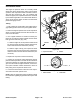
3. The terminator resistors (Fig. 127) can be tested us-
ing a digital multimeter (ohms setting). There should be
120 ohms resistance between terminals A and B of the
terminator resistors. Terminal C is not used.
Figure 127
Terminator
A
B
C
Resistor
4. If testing determines that resistor is faulty, replace re-
sistor assembly.
5. If the resistor tests correctly and a circuit problem still
exists, check wire harness (see Electrical Schematic
and Wire Harness Drawings in Appendix A − Foldout
Drawings in this manual).
6. After resistor testing is complete, make sure that re-
sistor is fully seated into wire harness connector and se-
cured to the wire harness with a cable tie.