
Service Manual


Multi Pro 5800 Page 6 − 79 Electrical System
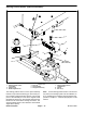
Fuel Pump (Gasoline Engines Only)
The electric fuel pump assembly used on Multi Pro 5800
machines with a gasoline engine is a combination posit-
ive displacement fuel pump and a fuel level sender. The
fuel pump assembly provides pressurized fuel to the en-
gine fuel rail in a return−less system and includes a reg-
ulator to maintain fuel pressure of approximately 40 PSI
(276 kPa). The fuel pump/level sender assembly is at-
tached to the top of the fuel tank (Fig. 115).
Electrical power for the fuel pump portion of the assem-
bly is available when the fuel pump relay is energized by
the engine ECU. The fuel pump electrical circuit is pro-
tected by a 15 Amp fuse. Both the fuel pump relay and
15A fuse are located in the engine power center.
When the ignition switch is turned to RUN, the engine
ECU energizes the fuel pump relay for approximately
three (3) seconds which allows the fuel system to be
pressurized. Once the engine is running, the fuel pump
relay is always energized.
Testing
NOTE: For information on testing the level sender por-
tion of the fuel pump/level sender assembly, see Fuel
Sender (Gasoline Engines Only) in this chapter.
1. Park machine on a level surface, stop engine and en-
gage parking brake. Remove key from ignition switch.
2. Remove engine shroud (attached to back of seat
base) to access fuel supply hose at engine.
CAUTION
The fuel supply hose will contain pressurized
fuel. Be careful when disconnecting fuel supply
hose. Always wipe up any spilled fuel before
starting the engine.
3. Disconnect the fuel supply hose from the engine fuel
rail.
A. Lift supply hose barb fitting lock up to unlock
fitting (Fig. 116).
B. Press barb fitting tab and pull fitting from fuel rail.
4. Install a fuel pressure gauge capable of measuring
50 PSI (350 kPa) to the disconnected hose.
1. Fuel tank
2. Gasket
3. Fuel pump/level sender
4. Flange head screw (4)
5. Tank cover
6. Cap
7. Fuel supply hose
8. Barb fitting
Figure 115
8
7
6
5
4
TO
FUEL
RAIL
3
2
13 to 65 in−lb
(1 to 7 N−m)
10 to 12 in−lb
(1 N−m)
1
Figure 116
1. Engine fuel rail
2. Barb fitting lock (down)
3. Barb fitting lock (up)
4. Barb fitting tab
LOCKED
UNLOCKED
1
1
2
3
4
4