
Service Manual


Multi Pro 5800Page 6 − 76Electrical System
Neutral Switch
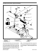
The neutral switch is located on the top side of the piston
(traction) pump (Fig. 110). The switch is closed when the
traction pedal is in the neutral position and opens when
the pedal is depressed in either direction (forward or re-
verse). The neutral switch is an input to the TEC.
Testing
The neutral switch and its circuit wiring can be tested as
a TEC input or qualifier using the InfoCenter Display
(see InfoCenter Display − Diagnostics Screen in this
chapter). If testing determines that the switch and circuit
wiring are not functioning correctly, proceed with the fol-
lowing test procedure:
1. Park machine on a level surface, stop engine, apply
parking brake and remove key from ignition switch.
2. Remove the rear undercarriage shroud (see Under-
carriage Shrouds in Chapter 9 − Chassis in this manual).
3. Locate neutral switch and disconnect wire harness
electrical connector from the switch.
4. With the use of a multimeter (ohms setting), the
switch function may be tested to determine whether
continuity exists between the terminals for each posi-
tion. The circuitry of the neutral switch is shown in the
chart below. Slowly push the traction pedal in a forward
and reverse direction while watching the multimeter. Al-
low the traction pedal to slowly return to the neutral posi-
tion Verify continuity between switch terminals (Fig.
109).
TRACTION PEDAL
POSITION
CIRCUITS
NEUTRAL NONE
FORWARD 1 + 2
REVERSE 1 + 2
Figure 109
NOTE: For neutral switch disassembly, assembly and
adjustment procedures, see the Eaton Model 72400
Servo Controlled Piston Pump Repair Information
(manual servo control assembly) at the end of this chap-
ter.
5. Replace switch if necessary.
1. Piston (traction) pump 2. Neutral switch
Figure 110
2
1
6. If the switch tests correctly and a circuit problem still
exists, check the wire harnesses (see Electrical Sche-
matics and Wire Harness Drawings and Diagrams in
Appendix A in this manual).
7. Connect the wire harness connector to the switch af-
ter testing.
8. Install the rear undercarriage shroud (see Undercar-
riage Shrouds in Chapter 9 − Chassis in this manual).