
Service Manual


Multi Pro 5800 Page 6 − 35 Electrical System
Using the InfoCenter Display for Troubleshooting
The Diagnostics − Input/Output screens of the InfoCen-
ter display can be very helpful when troubleshooting
machine operation issues (see Diagnostics − Input/Out-
put Screens in this chapter). Some of the electrical com-
ponents and the circuit wiring involved in various
machine operations can be evaluated using the Input/
Output screens prior to testing each component individ-
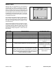
ually. The Input/Output screens show the current state
of the inputs, qualifiers and the outputs required to allow
the operation to proceed (Fig. 40).
PUMPS The components necessary to operate the
spray pump and the optional clean rinse pump.
BOOMS The components necessary to operate the
spray valves.
ENGINE RUN The components necessary to start
and run the engine.
CAUTION
It may be necessary to start and run the engine,
raise and lower the spray booms, or otherwise
operate the machine during the troubleshooting
process. Make sure the machine is in a well venti-
lated area and keep away from spray booms and
moving parts while troubleshooting.
If a machine operation is malfunctioning, the following
procedure can help identify the component or circuit
wiring causing the malfunction.
1. Park machine on a level surface, engage parking
brake and stop engine.
2. Set the ignition switch to the RUN/PREHEAT posi-
tion and navigate to the InfoCenter Diagnostic − Input/
Output Screen for the desired machine function.
3. Manually operate the input or qualifier component.
The component state on the InfoCenter display should
alternate ON and OFF as the component is switched
open and closed. If ON and OFF do not alternate during
component operation, the component or its circuit wiring
is faulty and should be tested (see Component Testing
in this chapter).
When the necessary inputs and qualifiers are in the cor-
rect position, the outputs identified on the Input/Output
screen should show as ON. If the output remains OFF,
a problem with TEC power (circuit wiring or fuse) may
exist, or the Toro Electronic Controller (TEC) or TEC
software may require reloading or replacement. Contact
your Authorized Toro Distributor for assistance.
Figure 40
1. Machine function
2. Inputs
3. Qualifiers
4. Outputs
1
2
3
4
A faulty output component will not be identified by the In-
put/Output screen. If all inputs, qualifiers and outputs
are correct for the machine operation selected, yet the
operation does not function as it should, the output com-
ponent or the circuit between the TEC and the output
component may be faulty. In this case, the controller out-
put is occurring but the faulty output component or cir-
cuit wiring is preventing the output from functioning. Test
the specific output and output wiring (see Component
Testing in this chapter).
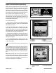
ENGINE RUN operation example:
Test the inputs: In this example, the inputs are the ig-
nition switch in the RUN position and the ignition
switch in the START position. If ON and OFF do not
correspond to the ignition switch (input) when moved
to the OFF, RUN and START positions, the switch or
the circuit wiring for the switch is faulty and should be
tested (see Component Testing in this chapter).
Test the qualifiers: In this example, the qualifiers are
the neutral switch, seat switch, parking brake switch
and spray pump switch.
Test the neutral switch (qualifier). If ON and OFF
do not alternate when the traction pedal is moved
from NEUTRAL to FORWARD and back to NEU-
TRAL, and from NEUTRAL to REVERSE and
back to NEUTRAL, the switch or the circuit wiring
for the switch is faulty and should be tested (see
Component Testing in this chapter).
Test the seat switch (qualifier). If ON and OFF do
not alternate when an operator sits in and raises
from the operator seat, the switch or the circuit
wiring for the switch is faulty and should be tested
(see Component Testing in this chapter).