
Operator's Manual


ElectricalSystem
Maintenance
ReplacingtheFuses
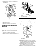
Thereare7fusesand1emptyslotintheelectrical
systemlocatedbeneaththedriverseat(Figure46).
20
10
10
15
15
MAX
MAX
MAX
MAX
30A
30A
10A
15A
15A
10A
(20A)
(20A)
G002242
5
6
7
8
4
1
23
Figure46
1.Spraysystem5.Leftboomactuatorthermal
breaker
2.Headlights6.Rightboomactuator
thermalbreaker
3.Cruisecontrol7.Openslot,foammarker
4.Power
8.Openslot
ServicingtheBattery
Warning
CALIFORNIA
Proposition65Warning
Batteryposts,terminals,andrelated
accessoriescontainleadandleadcompounds,
chemicalsknowntotheStateofCalifornia
tocausecancerandreproductiveharm.
W ash hands after handling .
Alwayskeepthebatterycleanandfullycharged.Use
apapertoweltocleanthebatteryandbatterybox.If
thebatteryterminalsarecorroded,cleanthemwitha
solutionof4partswaterand1partbakingsoda.Apply
alightcoatingofgreasetothebatteryterminalsto
preventcorrosion.
Voltage:12voltswith690coldcrankingAmpsat0
degreesF(-18degreesC)
RemovingtheBattery
1.Positionthesprayeronalevelsurface,settheparking
brake,stopthepump,stoptheengine,andremove
theignitionkey.
2.Removethebatteryretainerandfasteners(Figure47).
Figure47
1.Battery2.Batteryretainer
3.Disconnectthenegative(black)groundcablefrom
thebatterypost.
Incorrectbatterycableroutingcoulddamage
thesprayerandcablescausingsparks.Sparks
cancausethebatterygassestoexplode,
resultinginpersonalinjury.
•Always
disconnect
thenegative(black)
batterycablebeforedisconnectingthe
positive(red)cable.
•Always
r econnect
thepositive(red)battery
cablebeforereconnectingthenegative
(black)cable.
40