
Service Manual


6. Remove four (4) flange head screws and flange nuts
that secure pump to pump mount bracket.
7. Remove pump from machine.
8. If needed, loosen set screws in pump hub. Pull hub
from pump shaft. Locate and remove key from pump
shaft. Remove set screws from pump hub. Clean
threads of set screws and hub.
9. If needed, remove pressure dampener, tee fitting
(pressure),
and elbow fitting (pressure) from pump out-
let (Fig. 7).
10.If needed, remove suction dampener and tee fitting
(suction) from pump inlet (Fig. 7).
Figure 6
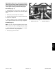
Installation (Fig. 5)
1. Pressure hose 2. Suction hose
NOTE: Coat all o–rings with vegetable oil before instal-
lation to reduce the chance of damage during assembly
.
2
13
1
3
5
4
8
9
10
11
14
12
15
17
6
7
6
1. Apply teflon tape to threads of removed tee fitting
(pressure), elbow fitting (pressure), and tee fitting (suc-
tion). Position new o–rings and gaskets on suction and
pressure fittings that were removed during disassembly
.
2. If removed, install tee fitting (suction) and suction
dampener to pump inlet. Orientate tee toward rear of
machine (Fig. 7).
3. If removed, install elbow fitting (pressure), tee fitting
(pressure), and pressure dampener to pump outlet.
Orientate elbow toward rear of machine (Fig. 7).
4. If pump hub was removed, apply anti–seize lubricant
16
9
to pump shaft. Install key in shaft and slide pump hub
onto shaft.
Figure 7
5. Position pump on pump mounting bracket and install
1. Spray pump 10. Pressure dampener
2. Pressure hose (1”) 1
1. Suction hose (1 1/2”)
flange head screws and flange nuts to pump and mount-
ing bracket. Leave fasteners loose.
3. Hose clamp 12. Hose clamp
4. Hose barb 13. Nut
5. Nut 14. Seal
6. Place coupling spacers into rubber coupling. Install
6. Gasket 15. Tee fitting (suction)
7. Tee fitting (pressure) 16. Suction
dampener
cap screws, flat washers, and lock nuts to secure rubber
8. Elbow fitting (pressure) 17. Hose barb
coupling to pump hub. Make sure that cap screw
9. O–ring
threads extend through lock nut.
7. Secure pump to mounting bracket by tightening
flange head screws and flange nuts.
8. If pump hub was removed, apply Loctite #242 (or
equivalent) to threads of pump hub set screws. Install
s
et screws into pump hub to secure hub to pump shaft.
9. Position front and rear guard plates to pump mount
bracket. Install and tighten flange head screw and
flange nut to guard plates. Install flange nuts to secure
guard plates to pump mount bracket.
10.Install pressure and suction hoses to correct barb fit-
tings (Fig. 6). Secure hoses with hose clamps.
Multi Pro 5600
Page 6 – 1
1
Spray System
2
1
Spray
System