
Service Manual


Multi Pro 5800 ChassisPage 9 − 13
Disassembly (Fig. 8)
1. Park machine on a level surface, stop engine, en-
gage parking brake and remove key from ignition
switch.
CAUTION
Before removing wheels or performing other
service, make sure machine is parked on a sol-
id, level surface such as a concrete floor. Al-
ways chock or block wheels. Use jack stands or
other appropriate load holding devices to sup-
port the raised machine. If the machine is not
properly supported, the machine may move or
fall, which may result in personal injury.
2. Jack front of machine off ground (see Jacking In-
structions in Chapter 1 − Safety in this manual). Support
machine to allow front suspension to hang freely from
machine.
3. Remove front wheels (see Wheel Assemblies in this
chapter).
4. Support axle to prevent it from shifting or falling.
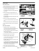
5. To remove leaf springs:
A. Loosen fasteners that secure springs to frame at-
tachment points.
B. Loosen and remove fasteners that secure spring
plate (item 3).
C. Remove shackles, bushings, shoulder bolts,
washers, lock washers and hex nuts from spring and
frame.
D. Remove leaf springs from machine.
IMPORTANT: If leaf spring replacement is needed,
always replace both springs for proper vehicle per-
formance.
6. If front axle removal is required, remove steering cyl-
inder (see Steering Cylinder Removal in Chapter 4 − Hy-
draulic System in this manual) and shock absorbers
from axle.
Assembly (Fig. 8)
1. If axle was removed from vehicle, position and sup-
port axle under frame.
2. To install leaf springs:
NOTE: When installing leaf springs, make sure front
axle and spring plate are centered on the screw head
and nut that secure spring leaves.
A. Apply a light coating of oil to bushing (item 8) and
loosely attach springs to frame with shackles, bush-
ings, shoulder bolts, washers, lock washers and hex
nuts. Do not fully tighten fasteners.
B. Install spring plate (item 3) to top of spring assem-
bly with curved ends upward.
C. Install and tighten cap screws (item 2), hardened
washers (item 4) and lock nuts (item 5) in a crossing
pattern until spring plate, leaf spring and axle are in
contact.
D. Fully tighten fasteners that secure springs to
frame.
E. Using a crossing pattern, tighten lock nuts
(item 5) that secure spring plate from 34 ft−lb (46
N−m). Using a crossing pattern, tighten lock nuts
from 69 to 85 ft−lb (94 to 115 N−m). Finally, use a
crossing pattern to check that lock nuts are all tight
from 69 to 85 ft−lb (94 to 115 N−m).
F. Apply medium strength wicking thread locker
(Loctite 290 or equivalent) to bolt threads.
3. If shock absorbers were removed, install shocks to
vehicle. Make sure that spacer is positioned between
shock and frame.
4. If steering cylinder was removed, install steering cyl-
inder (see Steering Cylinder in Chapter 4 − Hydraulic
System in this manual)
5. Install front wheels (see Wheel Assemblies in this
chapter).
6. Lower vehicle to ground.
7. Check front suspension and steering operation.
Make sure that steering components do not contact
hoses and/or wires throughout their entire range of mo-
tion.