
Service Manual


Multi Pro 5800Chassis Page 9 − 6
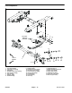
Wheel Assemblies
1. Front wheel assembly (2)
2. Rear wheel assembly (2)
3. Lug nut (5 per front wheel) 4. Lug nut (8 per rear wheel)
Figure 3
FRONT
RIGHT
55 to 75 ft−lb
(75 to 102 N−m)
70 to 90 ft−lb
(95 to 122 N−m)
1
2
3
4
Wheel Removal (Fig. 3)
1. Park machine on a level surface, stop spray pump,
stop engine and engage parking brake. Remove key
from ignition switch.
2. Chock front and rear of wheels that are not to be re-
moved.
3. Jack wheel that is to be removed off the ground (see
Jacking Instructions in Chapter 1 − Safety in this manu-
al). Support raised machine with jack stands.
4. Remove lug nuts and wheel assembly.
Wheel Installation (Fig. 3)
1. Install wheel assembly and secure with lug nuts.
WARNING
Failure to maintain proper wheel lug nut torque
could result in failure or loss of wheel and may
result in personal injury. Torque front wheel lug
nuts from 55 to 75 ft−lb (75 to 102 N−m), and rear
wheel lug nuts from 70 to 90 ft−lb (95 to 122 N−m).
2. Torque front lug nuts evenly in a crossing pattern
from 55 to 75 ft−lb (75 to102 N−m).
3. Torque rear lug nuts evenly in a crossing pattern from
70 to 90 ft−lb (95 to122 N−m).
4. Lower machine to ground.