
Service Manual


Multi Pro 5800Page 7 − 46ExcelaRate Spray System
Boom Section Bypass Shut−Off Valve and Agitation Throttle Valve Service
IMPORTANT: Make sure to remove and neutralize
chemicals from spray components before disas-
sembly. Wear protective clothing, chemical resist-
ant gloves and eye protection during repair.
Disassembly (Fig. 45)
1. Remove the screw and the knob from the valve.
2. Remove hoses, fittings, clamps and adapters as
necessary to access valve end caps.
3. Rotate the end caps counterclockwise (unscrew)
and remove the end caps.
4. Rotate the valve stem until the slot in the stem and
valve ball are in−line with the valve body and remove the
valve ball.
5. Remove the valve stem fork, seat, and remove the
valve stem assembly.
6. Inspect the valve seats (item 3). Replace compo-
nents as necessary.
Assembly (Fig. 45)
NOTE: Replace, do not reuse gaskets and O−rings.
Coat O−rings and gaskets with vegetable oil or silicone
grease before installation to reduce damage during as-
sembly.
1. Install new O−rings on stem assembly. Install stem
assembly, seat and fork.
2. Rotate the valve stem until the slot in the stem is in−
line with the valve body and install the valve ball.
3. Apply silicone grease to seals and O−rings on end
caps and install end caps. Tighten end caps until seated.
Do not over−tighten end caps.
4. Install hoses, fittings, clamps and adapters previous-
ly removed.
5. Install knob and screw.
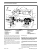
1. Valve body
2. End cap (male − fork)
3. Seat (2)
4. O−Ring (2)
5. O−Ring (2)
6. O−Ring (2)
7. Ball
8. Stem fork
9. O−Ring (2)
10. Stem
11. Washer
12. Stem seat
13. Knob
14. Screw
Figure 45
1
2
3
4
5
6
7
8
9
10
11
2
3
4
5
12
13
14
6