
Service Manual


Multi Pro 5800 Page 7 − 39 ExcelaRate Spray System
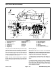
Spray Control Manifold Assembly
1. Boom section valve assy.
2. Agitation valve assy.
3. Valve mount
4. Flange head screw (6)
5. Flange nut (6)
6. Cap screw (4)
7. Cap screw (2)
8. Flange nut (2)
9. Washer/spacer (2)
10. High pressure filter bowl
11. Flow meter
12. Clamp (2)
13. Gasket (2)
14. O−ring (5)
15. Fork (5)
16. Hose (agitation supply)
17. Hose (boom supply − 3)
18. Hose (boom bypass)
19. Gasket (2)
20. Clamp (2)
21. Hose (agitation bypass)
22. Hose (supply from spray pump)
Figure 39
FRONT
RIGHT
11
12
12
13
13
14
14
14
15
15
16
17
18
19
19
20
20
1
2
3
4
4
5
6
7
8
9
10
21
22
23
The spray control manifold assembly includes the high
pressure spray product filter, the agitation valve with by-
pass valve, the flow meter, the three (3) boom section
valves with bypass valves, the pressure transducer and
the boom section bypass shut−off valve. Pressure
transducer testing information can be found in Chapter
6 − Electrical System in this manual.
NOTE: The spray control manifold may be configured
slightly different if the machine has any optional spray
system kits installed (e.g. foam marker, hose reel, educ-
tor, etc).
Removal (Fig. 39)
IMPORTANT: Make sure to remove and neutralize
chemicals from spray components before disas-
sembly. Wear protective clothing, chemical resist-
ant gloves and eye protection during repair.
1. Park machine on a level surface, stop engine, en-
gage parking brake and remove key from the ignition
switch.
2. Label wire harness connectors for proper installation
after repairs are completed (agitation valve, three (3)
boom section valves, flow meter sensor, pressure trans-
ducer). Disconnect wire harness connectors from spray
control manifold as needed.