
Service Manual


Multi Pro 5800 Page 6 − 89 Electrical System
Resistor Assemblies
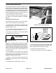
All Multi Pro 5800 machines include at lease one 75 ohm
resistor assembly. The resistor assembly can be identi-
fied by its gray color, resistor symbol and Toro part num-
ber on the end of the resistor assembly body (Fig. 130).
The resistor assembly plugs into the vehicle wire har-
ness (see Electrical Schematic and Wire Harness Draw-
ings in Chapter 11 − Foldout Drawings).
All machines include a 75 ohm resistor in the engine
start circuit. The resistor is located under the instrument
panel to the left of the steering column.
On machines with diesel engines, two (2) additional re-
sistors are used in the instrument panel warning light cir-
cuit. The resistors are located under the instrument
panel near the fuel gauge.
Testing
1. Park machine on a level surface, stop engine and en-
gage parking brake. Remove key from ignition switch.
2. Locate resistor assembly to be tested and remove
cable tie that secures resistor to wire harness. Unplug
the resistor from the wire harness for testing.
3. The resistor can be tested using a digital multimeter
(ohms setting). The resistance across the resistor ter-
minals should be approximately 75 ohms.
4. If testing determines that resistor is faulty, replace re-
sistor assembly.
5. If the resistor tests correctly and a circuit problem still
exists, check wire harness (see Electrical Schematic
and Wire Harness Drawings in Appendix A − Foldout
Drawings in this manual).
6. After resistor testing is complete, make sure that re-
sistor is fully seated into wire harness connector and se-
cured to the wire harness with a cable tie.
1. Resistor assembly 2. End of resistor body
Figure 130
1
2