
Service Manual


Multi Pro 5800Page 6 − 64Electrical System
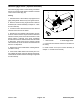
Boom Control Switches
Three (3) identical boom control switches are used on
the Multi Pro 5800 to turn the spray valve for the individu-
al boom sections on or off. The boom control switches
are inputs to the TEC. The boom switches are located
on the control console (Fig. 89).
With the ignition switch in the START or RUN position,
a continuous supply of voltage is applied to the Close
signal wire of the spray valve actuators, closing the
boom spray valves. When the master boom switch is set
to the ON position, a boom control switch is set to the ON
position and all spray system conditions are met, the
TEC supplies voltage to the Open signal wire of the
boom spray valve actuator to open the boom spray
valve.
Testing
The boom control switches and their circuit wiring can be
tested as TEC inputs or qualifiers using the InfoCenter
Display (see InfoCenter Display − Diagnostics Screen in
this chapter). If testing determines that the switch and
circuit wiring are not functioning correctly, proceed with
the following test procedure:
1. Park machine on a level surface, stop engine and en-
gage parking brake. Remove key from ignition switch.
2. Remove console cover(s) to gain access to switch to
be tested (see Console Assembly in Chapter 9 − Chas-
sis in this manual).
3. Locate the switch to be tested and disconnect the
wire harness electrical connector from the switch.
4. With the use of a multimeter (ohms setting), the
switch functions may be tested to determine whether
continuity exists between the various terminals for each
position. The switch terminals are marked as shown
(Fig. 66) and the circuitry of the switch is shown in the
chart (Fig. 88). Verify continuity between switch termi-
nals.
SWITCH
POSITION
CLOSED
TERMINALS
OPEN
TERMINALS
OFF 2 + 1, 5 + 4 2 + 3, 5 + 6
ON 2 + 3, 5 + 6 2 + 1, 5 + 4
Figure 88
5. Replace switch if necessary.
6. If the switch tests correctly and a circuit problem still
exists, check the wire harnesses (see Electrical Sche-
matics and Wire Harness Drawings and Diagrams in
Appendix A in this manual).
1. Control console
2. Left side boom switch
3. Center boom switch
4. Right side boom switch
Figure 89
1
2
3
4
Figure 90
BACK OF SWITCH
7. Connect the wire harness connector to the switch af-
ter testing is complete.
8. Install control console covers (see Console Assemb-
ly in Chapter 9 − Chassis in this manual).
NOTE: Boom control switch terminals 1, 4, 5 and 6 are
not used on Multi Pro 5800 machines.