
Service Manual


Multi Pro 5800 Page 6 − 13 Electrical System
Operator’s Information
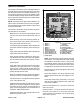
The operator’s information screen is displayed about 10
seconds after the ignition switch has been turned from
the OFF position to the ON or START position (Fig. 13).
The operator’s information screen is the “default” screen
as it will be displayed during normal machine operation.
See the machine Operators Manual or Software Guide
for additional information.
NOTE: Depending on the spray system installed or op-
eration mode, all indicators and icons may not appear.
See the individual spray system chapters in this manual
for specific information.
The operator’s information screen provides the follow-
ing information to the operator:
Master Boom: Icon (all three booms) appear across
the top of the screen when master boom switch is
ON.
Boom Sections; Icon (boom with spray pattern) ap-
pears when master boom switch is ON and one or
more spray boom switches are ON.
Actual Spray System Application Rate: Indicates the
actual rate at which the sprayed product is being ap-
plied.
Target Spray System Application Rate: Indicates the
target rate that the user desires.
Spray System Pressure: Indicates the spray pres-
sure when the boom sections are ON or the agitation
pre−set pressure when the boom sections are OFF.
Vehicle Speed
Spray Tank Volume: Displays the amount of product
remaining in the spray tank. This is a calculation
based on the volume manually entered when the
tank is filled, then reduced by the amount of product
passing through the flow meter.
Brake: Icon appears whenever the brake is applied,
and stays on when the parking brake is engaged.
Operator Presence: Icon appears when the operator
is out of the operator seat.
Application Rate Selected: The selected pre−set ap-
plication rate number is displayed. This represents
the number of the pre−set rate, not the actual rate of
spray product being applied. See Set Rates in this
chapter for additional information.
Application Rate Boost: The + appears when the ap-
plication rate boost is active.
1. Button 1
2. Button 2
3. Button 3
4. Button 4
5. Button 5
6. Master boom(active
7. Boom section active
8. Actual application rate
9. Target application rate
10. Spray system pressure
11. Vehicle speed
12. Spray tank volume
remaining
13. Brake applied
14. Operator presence
15. Pre−set application rate
selected
16. Application boost active
17. Spray pump enabled
18. Agitation enabled
19. Tank Rinse enabled
Figure 13
1
2
3
4
5
6
7
9
8
10
12
19
17
18
16
11
13
14
15
NOTE: When the spray pump is enabled, press and
hold buttons 1 and 5 simultaneously while viewing
the Operator’s Information screen to activate the
boost feature. Boost is active only as long as the but-
tons are depressed. The spray system returns to the
set application rate when the buttons are released.
Spray Pump: Icon (spray tank) appears when spray
pump is enabled.
Spray Tank Agitation: Icon (spray tank with mixing
pattern) appears when spray tank agitation is en-
abled.
Clean Tank Rinse Pump (optional kit): Icon (spray
tank with spray pattern) appears when clean tank
rinse pump is enabled.
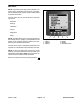
Press and hold button 5 for 3 seconds to access the
main menu screen.
Press any button 1−4 to expose the menu bar. From the
menu bar, press button 2 to access the spray area
screen−total area or press button 3 to access the spray
area screen−sub area.