
Operator's Manual


g191300
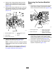
Figure121
1.Flange(couplingadapter)3.Section-manifoldvalve
2.Flange(section-manifold
valve)
4.Flangeclamps
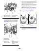
4.Forleftorrightsection-valvemanifolds,remove
the2ange-headbolts(1/4x3/4inch)and
2angelocknuts(1/4inch)thatsecurethe
section-valvemanifoldtothevalvesupport
(Figure122).
g191304
Figure122
1.Flangelocknut(1/4
inch—leftandright
section-valvemanifold
positions)
4.Flange(couplingadapter)
2.Section-bypassvalve5.Gasket
3.Quick-connecttting
(section-valvemanifold)
6.Flange-headbolt(1/4x
3/4inch—leftandright
section-valvemanifold
positions)
5.Movethesection-valvemanifoldandgaskets
downtoclearthesection-bypassvalveandthen
awayfromthemachine(Figure122).
Note:Ifneeded,loosenthemountinghardware
fortheleftorrightsection-valvemanifoldsas
neededtoprovideclearance.
Note:Retaintheangeclamps,gasketsand
quick-connectpinsforinstallationinInstalling
theAgitation-ManifoldValve(page87).
CleaningtheManifoldValve
1.Positionthevalvestemsothatitisintheclosed
position(Figure123B).
g027562
Figure123
1.Valveopen2.Valveclosed
2.Removethe2end-cap-ttingassembliesfrom
eachendofthemanifoldbody(Figure124and
Figure125).
84