
Operator's Manual


g014220
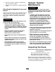
Figure102
1.Flatontheactuatorrod5.Eyeletadjusted
2.Jamnut
6.Eyeletpositionfor
assembly
3.Eyelet7.Jamnuttightenedtolock
newposition
4.Jamnutloosened
6.Turntheeyeletrodintheactuatorrodtoshorten
orlengthentheextendedactuatortothedesired
position(Figure102).
Note:Youmustturntheeyeletrodinhalfor
completerevolutionssothatyoucanassemble
therodtotheboom.
7.Oncethedesiredpositionhasbeenachieved,
tightenthejamnuttosecuretheactuatorand
eyeletrod.
8.Raisetheboomtoalignthepivotwiththe
actuatorrod.
9.Whileholdingtheboom,insertthepinthrough
bothboompivotandactuatorrod(Figure101).
10.Withthepininplace,releasetheboomand
securethepinwiththecotterpreviously
removed.
11.Repeattheprocedureforeachactuatorrod
bearing,ifnecessary.
InspectingtheNylonPivot
Bushings
ServiceInterval:Every400hours/Yearly(whichever
comesrst)
1.Parkthemachineonalevelsurface,engagethe
parkingbrake,shutoffthepump,shutoffthe
engine,andremovethekey.
2.Extendtheouter-boomsectionstothespray
positionandsupporttheboomsusingstandsor
strapsandliftingequipment.
3.Withtheweightoftheboomsupported,remove
theboltandnutsecuringthepivotpintothe
boomassembly(Figure103).
g002017
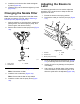
Figure103
1.Nylonbushings3.Bolt
2.Pivotpin
4.Removetheboltandnutthatsecurethepivot
pin,andremovethepin(Figure103).
5.Removetheboomandpivotbracketassembly
fromthecenterframetoaccessthenylon
bushings.
6.Removeandinspectthenylonbushingsfrom
thefrontandbacksidesofthepivotbracket
(Figure103).
Note:Replaceanywornordamagedbushings.
7.Placeasmallamountofoilonthenylon
bushings,andinstallthemintopivotbracket
(Figure103).
8.Installtheboomandpivotbracketassemblyinto
thecenterframe,aligningtheholes(Figure103).
9.Installthepivotpinandsecureitwiththebolt
andnutremovedinstep4.
10.Repeatsteps2through9fortheother
outer-boomsection.
75