
Service Manual


Multi Pro 5800 Page 8 − 91 GeoLink Spray System
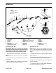
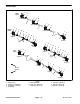
Agitation Line
1. Hose barb (3)
2. O−ring (3)
3. Fork (3)
4. Clamp (2)
5. Agitation hose 32 in. (81 cm)
6. Clamp (16)
7. Agitation hose 16 (40 cm)
8. Tee (3)
9. Agitation hose 14 (35.5 cm) (3)
10. Elbow
11. Agitation hose 5 (12.7 cm) (4)
12. Adapter (4)
13. O−ring (4)
14. Nozzle (4)
15. Nut (4)
16. Seal (4)
17. Bulkhead (4)
18. Fork (4)
19. Clamp
20. Agitation throttle valve
21. Cap screw (4)
Figure
108
FRONT
RIGHT
13
14
15
16
17
18
19
20
2
2
21
1
1
1
2
3
3
4
5
6
6
6
6
6
4
6
7
8
9
10
12
11
20 to 24 ft−lb
(27 to 33 N−m)
Disassembly (Fig. 108)
IMPORTANT: Make sure to remove and neutralize
chemicals from tank and other components before
disassembly. Wear protective clothing, chemical re-
sistant gloves and eye protection during repair.
1. Park machine on a level surface, stop engine, en-
gage parking brake and remove key from the ignition
switch.
2. Label hoses that are to be disconnected for assem-
bly purposes.
3. Remove agitation line components as necessary.
Discard all removed O−rings and gaskets.
Assembly (Fig. 108)
NOTE: Replace, do not reuse gaskets and O−rings.
Coat O−rings and gaskets with vegetable oil or silicone
grease before installation to reduce damage during as-
sembly.
1. Replace all removed O−rings and gaskets and as-
semble drain line.
2. Using labels placed during disassembly, install dis-
connected hoses and secure with hose clamps.
3. Make sure that agitation throttle valve is open and
secured to sprayer.
4. Check spray system for leaks. Repair all leaks be-
fore returning the sprayer to service.