
Service Manual


Multi Pro 5800 Page 8 − 75 GeoLink Spray System
Disassembly
IMPORTANT: Make sure to remove and neutralize
chemicals from pump before disassembly. Wear
protective clothing, chemical resistant gloves and
eye protection during pump repair.
NOTE: Many pump components can be easily re-
versed. During disassembly, make note of component
position (e.g. valve cover, pump valve, diaphragm) to
assure correct assembly.
1. Remove plugs (item 14) and seals from pump to al-
low all fluid to be drained from pump. Install seals and
plugs after draining is complete.
2. Thoroughly clean exterior of pump.
3. For assembly purposes, use marker to identify loca-
tion of all valve covers on pump housing.
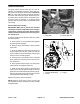
NOTE: Pump bracket on model 363 pumps (item 26
Fig. 92) is secured to pump with two (2) longer bolts on
upper valve covers. Pump foot for both model 363 and
364 pumps (item 16) is secured to pump with four (4)
longer bolts on lower valve covers.
4. Remove hex bolts that retain valve covers (item 3) to
pump. Separate and remove valve covers from pump.
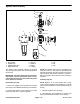
NOTE: The two (2) pump inlet valves in the upper head
positions (either side of suction port) are different than
the rest of the valves used in the pump (item 25 Fig. 92).
These two (2) valves are white in color.
5. Remove and discard all valves (inlet and outlet) and
valve O−rings from pump. During valve removal, note
location and orientation of valves.
6. Remove hex bolt, diaphragm disc, diaphragm and
diaphragm backing disc from each connecting rod. Dis-
card all diaphragms.
IMPORTANT: If pump sealing surfaces are not thor-
oughly cleaned, leakage can occur that will ad-
versely affect pump performance.
7. Thoroughly clean all valve, diaphragm and O−ring
seats in the valve covers and pump valve chambers.
8. Check the crankshaft for sufficient grease. Also,
visually inspect crankshaft assembly for any signs of ex-
cessive wear or damage. Check that crankshaft turns
freely. If crankshaft bearings are loose, rough or worn,
crankshaft bearings should be replaced.
Crankshaft Bearing Service
1. For assembly purposes, use marker to identify loca-
tion of all connecting rods.
2. Remove three (3) hex bolts that secure pump casting
halves together.
3. To separate the pump castings:
A. From the non−driven side of the pump, place a
spacer or socket on crankshaft end.
B. Using dead−blow hammer and tap the spacer to
separate the pump castings.
C. Once a gap is created between the castings,
carefully pry pump castings apart.
4. Remove connecting rods and inspect the rod bear-
ing surfaces which should be clean and smooth. Re-
place any of the connecting rods that have evidence of
scoring, wear or damage.
5. Remove crankshaft with bearings and spacers
(items 20 −22) from pump.
6. Press ball bearings from crankshaft and pump cast-
ings.
7. Remove seals from pump castings.
8. Clean crankshaft and internal surfaces of pump cast-
ings.
9. Pack new bearings with Mobil XHP 461 lithium−com-
plex high temperature grease.
10.Press new bearings into pump castings.
11. Install connecting rod bearings on crankshaft:
A. Pressing on bearing inner race, install first con-
necting rod bearing onto crankshaft.
B. Place bearing spacer (item 22) onto crankshaft
and then press second bearing onto crankshaft.
12.Install seals into pump castings. Seal face should be
flush with casting.
13.Position the pump casting (item 11) with the seal side
down.
14.Place connecting rod spacer (item 20) and then
crankshaft assembly into pump casting. Make sure that
non−driven end of crankshaft is inserted into the pump
casting.