
Setup Instructions


2.Plumbthehosefromthebottomoftherinsetankto
therinsetankvalvesothatthehosewrapsaround
thepumpandisroutedalongthemainpumphose.
3.Routetherinsetanksuctionhosebehindthevalve
assemblytotherinsetanksideoftherinsetankvalve.
Important:Installtherinsetanksuctionhose
sothatthecheckvalvearrowshowsthedirection
ofowfromtherinsetanktotherinsetankvalve.
4.Securethehosetotherinsetankusingthesmall
retainerforkinlooseparts.
5.Installthehosetotheinputsideoftherinsetank
valveandsecureitwiththeretainerforkincluded
inlooseparts.
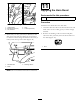
6.Usetheplastictieslocatedinloosepartstosecure
therinsetanksuctionhosetothemainpumphose
asshowninFigure26.
InstallingtheRinseNozzleHose
1.Locaterinsenozzlehoseassemblysetasideearlier.
2.Installthehosetotheinputsideoftherinsenozzle
valve.
3.Plumbthehoseunderandbehindthemainpump
andmaintanksuctionhose,tothebarbedelbow
ttingintherinsetube(Figure26).
4.Securetherinsenozzlehosetothe60degreeelbow
ttingbythreadingthesmallretainernutoverthe
elbowtting.Makesurethesmall,clearO-ringis
seatedinthesmallretainernutattheendoftherinse
nozzlehose.Handtighten.
9
InstallingtheBatteryCover
Fasteners
Partsneededforthisprocedure:
2
Flangebolt(5/16x3/4inch)
2
Flangenut(5/16inch)
Procedure
Replacethebatterycoverhandknobswithfasteners
fromtheCEkit.
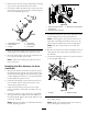
1.Loosenandremovethetwohandknobssecuring
batterycovertobatterybase(Figure27).
Figure27
1.Handknob3.Batterycover
2.Battery
2.Installthetwoangebolts(5/16x3/4inch)and
twoangenuts(5/16inch)inplaceoftheremoved
handknobtosecurethebatterycover.
10
InstallingtheHorn
Partsneededforthisprocedure:
1Horn
1
Bolt(5/16x3/4inch)
1
Locknut(5/16inch)
Procedure
Preparethemachinefortheinstallationofthehorn.
1.Drillahole,8.5mm(11/32inch)indiameter,in
thevehicleframeundertheoorboard.Thehole
shouldbe4cm(1-1/2inches)downfromtheframe
topand5cm(2inches)fromthefrontoftheframe
(Figure28).
2.Securethehorntotheframeusingabolt(5/16x
3/4inch)andalocknut(5/16inch)asshownin
Figure28.
14