
Installation Instructions


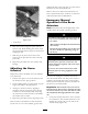


2. Use the g raphic to locate the set of mounting
holes the center boom will be installed to for
y our mac hine ( Figure 13 ).
Figure 13
Right side boom frame upright shown
1. Mounting holes for 1200
series turf sprayers
2. Mounting holes for 5700
turf sprayers
Note: T he upper set of holes are for booms
designed for nozzles 20 inc hes off the g round.
T he lo w er set of holes can be used to mount
booms so that the nozzles will be 18 inc hes
off the g round.
3. Install center boom assembly to the uprights
using four flang e bolts (1/2 x 1-1/4 inc hes)
and four flang e n uts (1/2 inc h) ( Figure 14 ).
Figure 14
1200 series turf sprayers install shown
1. Boom upright
3. Flange bolt (1/2 x 1-1/4
inches)
2. Center boom
4. Flange nut (1/2 inch)
4. Mak e electrical connections for boom actuators
to newly routed connectors .
5. P o w er on the system and use the boom lift
switc hes to extend the boom actuator rods .
T his is to allo w the left and right boom
extensions to be installed.
6. R emo v e the four bolts , four w ashers and four
n uts on the hing e plate .
7. Install the extension boom to the center boom
at the hing e plate using four bolts , four w ashers
and four n uts remo v ed in ste p 6 as sho wn in
Figure 15 .
Note: Ensure all spra y tur rets are facing to
the rear .
Figure 15
1. Center boom assembly 4. Bolt
2. Boom extension
5. Washer
3. Hinge plate
6. Nut
8. R e peat ste p 7 on the other side of the center
boom assembly with the opposing boom
extension.
Note: Ensure all spra y tur rets are facing to
the rear .
12