
Operator's Manual


RemovingtheValveActuator
1.Positionthesprayeronalevelsurface,engage
theparkingbrake,shutoffthepump,shutoffthe
engine,andremovethekey.
2.Removethe3-pinconnectorofthevalve
actuatorfromthe3socketelectricalconnector
ofthesprayerharness.
3.Removetheretainerthatsecurestheactuatorto
themanifoldvalvefortheratecontrol,agitation,
mastersection,orsectionvalve(Figure112).
Note:Squeezethe2legsoftheretainer
togetherwhilepushingitdown.
Note:Retaintheactuatorandretainerfor
installationinInstallingtheValveActuator(page
88).
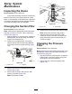
g028237
Figure112
Section-ValveActuatorShown(theagitation-valveactuator
issimilar)
1.Valveactuator(section
valveshown)
3.Stemport
2.Retainer
4.Removetheactuatorfromthemanifoldvalve.
RemovingtheRateControl
ManifoldValve
1.Remove2angeclampsand2gasketsthat
securethemanifoldfortheratecontrolvalve
(Figure113)tothepressurelterandagitation
valve.
Note:Retaintheangeclampsandgaskets
forinstallationinInstallingtheRateControl
ManifoldValve(page84).
g033584
Figure113
1.Flange(pressurelter
head)
4.Flangeclamp
2.Manifold(ratecontrol
valve)
5.Gasket
3.Flange(agitationvalve)6.3-pinconnector(valve
actuator—ratecontrol
valve)
2.Removetheretainerthatsecuretheoutlettting
tothemanifoldcouplingfortheratecontrolvalve
(Figure114).
78