
Operator's Manual


6
InstallingtheTankSkid
Partsneededforthisprocedure:
1Tankandskidassembly
2
Clevispins
2Taperedclevispin
2Hairpins
4Lynchpins
2
Bolt(1/2x1-1/2inches)
2
Nuts(1/2inch)
Procedure
DANGER
Thesprayertankassemblyrepresentsa
storedenergyhazard.Ifnotproperlyretained
wheninstallingorremovingtheassembly,
itcanmoveorfallandinjureyouorother
bystanders.
Usestrapsandanoverheadlifttosupport
thesprayertankassemblyduringinstallation,
removal,oranymaintenancewhenthe
retainingfastenersarebeingremoved.
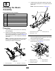
1.Usingalift,raisethetankskidassembly(Figure
9)andpositionitoverthevehicleframewiththe
pumpandvalveassembliesfacingrearward.
Note:Haveanotherpersonhelpyouperform
thefollowingsteps.
g023738
Figure9
1.Rearliftpoint2.Frontliftpoint
2.Slowlylowerthetankskidtotheframe.
3.Connectthenegativebatterycableandstartthe
vehicletoenergizethehydraulicpumps.
4.Extendtheliftcylinderstothebracketsonthe
tankskid,andalignthecylinderarmswiththe
holesinthetankskidbrackets(Figure10).
g022353
Figure10
1.Hairpin
3.Liftcylinders
2.Clevispin
5.Usetheclevispinandhairpintosecurethe
tankskidtotheliftcylindersonbothsidesofthe
vehicle.
6.Lineupthepivotlugattherearofthetankskid
assemblywiththeopeningattheendofthe
vehicleframe(Figure11).
g022354
Figure11
1.Taperedclevispin2.Lynchpin
7.Installataperedclevispinand2lynchpinsto
thepivotlugtosecurethetankassemblytothe
frame(Figure11).
8.Extendtheliftcylinderstoraisethetankand
supportitsweight.
Note:Disconnectthetankassemblyfromits
overheadsupport.
15