
Service Manual


Removal (Fig. 6) 4. Remove set screws from pump hub. Clean threads
IMPORTANT: Make sure to neutralize and remove
chemicals
from pump and hoses before loosening
and removing spray system components.
1. Park machine on a level surface, stop engine, en-
gage parking brake, and remove key from the ignition
switch.
2. Loosen hose clamp that secures suction hose (item
1
1) to hose barb (item 14). Pull suction hose from hose
barb.
3. Loosen hose clamp that secures pressure hose
(item 8) to hose barb (item 5). Pull pressure hose from
hose barb.
4. Remove lock nuts, flat washers, cap screws, and
spacers that secure rubber coupling to pump hub.
5. Remove cap screws and flange nuts that secure
pump to pump mount bracket.
6. Remove pump from machine.
7. Loosen set screws in pump hub. Pull hub from pump
shaft. Locate and remove key from pump shaft.
8. Remove pressure dampener
, tee (pressure), and el-
bow (pressure) from pump outlet.
9. Remove suction dampener and tee (suction) from
pump inlet.
Installation (Fig. 6)
NOTE: Coat all o–rings with vegetable oil before instal-
lation to reduce the chance of
damage during assembly.
1. Apply PTFE tape to threads of tee (pressure), elbow
(pressure),
and tee (suction). Position new o–rings and
gaskets on suction and pressure fittings that were re-
moved during disassembly.
2. Install tee (suction) and suction dampener to pump
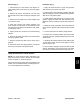
inlet. Orientate tee toward rear of machine (Fig. 7).
3. Install elbow (pressure), tee (pressure), and pres-
sure dampener to pump outlet. Orientate elbow toward
rear of machine (Fig. 7).
of set screws and hub.
5. Apply anti–seize lubricant to pump shaft. Install key
in shaft and slide pump hub onto shaft.
6. Position pump on pump mounting bracket. Install
cap screws and flange nuts to pump and mounting
bracket. Leave fasteners loose.
7. Place coupling spacers into rubber coupling. Install
c
ap screws, flat washers, and lock nuts to secure rubber
coupling to pump hub. Make sure that cap screw
threads extend through lock nut.
8. Secure pump to mounting bracket by tightening c
ap
screws and flange nuts.
9. Apply Loctite #242 (or equivalent) to threads of
pump
hub set screws. Install set screws into pump hub to se-
cure hub to pump shaft.
10.Install pressure and suction hoses to correct barb fit-
tings. Secure hoses with hose clamps.
2
1
Figure 7
1. Elbow (pressure) 2. Suction hose
Spray
System
Multi Pro 1200/1250
Page 6 – 13 (Rev. B)
Spray System