
Operator's Manual


39
m–5639
1
2
3
5
5
6
4
52 inches
(132 cm)
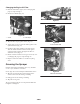
Figure 51
1. Tire center line—back
2. Tire center line—front
3. Axle center line
4. Fixture
5. Axle center line distance
6. 6 inches (15 cm) ruler
5. If the measurement does not fall within the specified
range,
loosen the jam nuts at both ends of the tie rods
(Fig. 52).
2
1
m–5320
1
Figure 52
1. Jam nut 2. Tie rod
6. Rotate both tie rods to move the front of the tire inward
or outward.
Note: The tie rods should be the same length when you are
finished.
7. Tighten the tie rod jam nuts when the adjustment is
correct.
8. Ensure that there is full travel of the steering wheel in
both directions.
Servicing the Drive Belt
Checking the Drive Belt
Check the condition and tension of the drive belt after the
first day of operation and every 200 operating hours
thereafter.
1. Position the sprayer on a level surface, set the parking
brake, move the range selector to the Neutral position,
stop the pump, stop the engine, and remove the ignition
key.
2. Rotate and inspect the drive belt for excessive wear or
damage. Replace the belt if necessary.
1
2
2 3
1
Figure 53
1. Drive belt
2. Belt guide (only one
shown)
3. Primary clutch
4. Secondary clutch
Replacing the Drive Belt
1. Loosen the 2 belt guides near the secondary clutch
(Fig. 53).
2. Rotate and route the belt over the secondary clutch
(Fig. 53).
3. Remove the belt from the primary clutch (Fig. 53).
4. Place the new belt over the primary clutch (Fig. 53).
5. Rotate and install it over the secondary clutch (Fig. 53).
6. Tighten the belt guides 3/16 inch (1/2 cm) from the
pulley.