
Operator's Manual


16
FLOW METER:
Once per season the Flow Meter should be flushed
and cleaned. Perform this procedure more often
if suspension type products are being sprayed.
1. Thoroughly rinse and drain the entire spraying
system.
2. Remove Flow Meter from Sprayer and flush
with clean water to remove any chemicals.
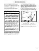
3. Remove flange bolts from the Flow Meter. See
FIG. 7.
8. Using a low pressure 5 PSI [50 kPa] jet of air,
verify that the turbine spins freely. If there is drag,
loosen the turbine stud on the bottom of the turbine
hub by 1/3 turn, until the turbine spins freely.
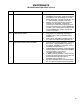
PROCEDURE TO TEST THE FLOW METER
CABLE:
Disconnect the Console Control Cable from the
Flow Meter Cable. Hold the cable connector so
that the key way is pointing in the 12 oclock
position. See FIG. 8.
MAINTENANCE
FIG. 7
1. Flange Bolt 4. Transducer
2. Turbine Hub 5. Turbine Stud
3. Turbine 6. O-Ring, Viton
4. Remove the turbine hub and turbine from
inside Flow Meter.
5. Clean turbine and turbine hub of metal filings
and any other foreign material, such as wettable
powders. Confirm that turbine blades are not
worn. Hold turbine hub and turbine in your hand
and spin turbine. It should spin freely with very
little drag.
6. If transducer assembly is replaced or if turbine
stud is adjusted or replaced, verify the turbine fit
before reassembling. Hold turbine hub with
turbine on transducer. Spin turbine by blowing
on it. Tighten turbine stud until turbine stalls.
Loosen turbine stud 1/3 turn: the turbine should
spin freely.
7. Reassemble Flow Meter.
FIG. 8
VOLTAGE READINGS
2 oclock to 6 oclock (+5 VDC)
2 oclock to 10 oclock (+5 VDC)
1. Record METER CAL value
2. Enter a METER CAL number of one (1) in key
labeled:
METER
CAL
5
3. Depress key labeled:
TOTAL
VOLUME
4. Place MASTER and BOOM switches ON.
5. With small jumper wire (or paper clip), short
between 2 oclock and 6 oclock sockets with a
short - no short motion. Each time a contact is
made, the TOTAL VOLUME total should increment
up 1 or more counts.
6. If TOTAL VOLUME does not count up. Replace
defective cable.
7. Perform above voltage checks.
8. If cables all test good, refer to test Flow Meter.
NOTE: After testing is complete, re-enter
correct METER CAL number before spraying.
10 O’CLOCK
6 O’CLOCK
2 O’CLOCK
KEYWAY
(POWER)
(SIGNAL)
(GROUND)
1127