
Operator's Manual


7.Placethespeed-controlleverintheneutralposition.
WARNING
Electricalsystemwillnotperformproper
safetyshutoffwithOperatorPresenceControl
(OPC)leversheldinplace.
•MakesureOperatorPresenceControl
(OPC)leversareworkingwhenadjustment
iscompleted.
•NeveroperatethisunitwithOperator
PresenceControl(OPC)leversheldin
place.
8.Loosenthefrontadjustingnutonlefthydrocontrol
linkageasshowninFigure39.
9.Turntheleftrearadjustingnutcounterclockwiseuntil
thewheelrotatesforward(Figure39).
10.Turntherearadjustingnutclockwise1/4ofaturnata
time.Thenmovethespeed-controlleverforwardand
backtoneutral.Repeatthisuntiltheleftwheelstops
rotatingforward(Figure39).
11.Turntherearnutanadditional1/2turnandtightenthe
frontadjustingnut.
Note:Makesurethattheatpartofthelinkageis
perpendiculartothepinpartoftheswivel.
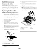
1
1
2
4
3
4
5
G024291
Figure38
1.Hydrocontrollinkage
4.Swivel
2.Frontnut5.90degrees
3.Rearnut
12.Afteradjustingthelefthydrocontrollinkage,move
thespeed-controlleverforwardandthenbacktothe
neutralposition.
13.HoldtheOPCleversdown.
Note:TheOPCleversmustbehelddownwhenever
thespeed-controlleverisoutoftheneutralpositionor
theenginewillstop.
14.Makesurethatthespeed–controlleverisintheneutral
positionandthetiredoesnotrotate.
15.Repeattheadjustmentifneeded.
Figure39
1.Hydrocontrollinkage3.Rearadjustingnut
2.Frontadjustingnut
4.Controlarm
Note:Ifinconsistentneutraloccurs,checktobe
surethatbothspringsareproperlytightenedonthe
speed-controlleverundertheconsole,especiallythe
rearpivotspring.Repeattheaboveadjustmentsif
necessary(Figure40).
Figure40
1.Speed-controllever
3.spring
2.Rearpivotspring
AdjustingtheRightSideLinkage
1.Placethespeed-controlleverintheneutralposition.
2.Placetherightdriveleverinthefullforwardposition.
3.Adjusttherightsidelinkagebyturningthequicktrack
knobcounterclockwiseuntilthetirebeginstorotate
forward(
Figure41).
32