
Operator's Manual


9.Loosenthenutagainsttheyoke(Figure57).
10.Removetheassistarmlinkfromtheassistarmand
rotatethelinktoadjustthelength.
11.Installtheassistarmlinkintotheassistarmandsecure
itwiththehairpincotterpin(Figure58).
12.Checkiftheassistarmhitsagainstthestopscorrectly.
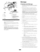
AdjustingthePTOSafetySwitch
1.Disengagetheblade-control(PTO)leverandsetthe
parkingbrakes.
2.Stoptheengineandwaitforallmovingpartstostop
beforeleavingtheoperatingposition.
3.Disengagetheblade-controllever(PTO).Makesure
thattheassistarmisagainstthefrontassistarmstop.
4.Ifneeded,adjusttheblade-safetyswitchbyloosening
theboltsholdingtheswitchbracket(Figure59).
5.Movethemountingbracketuntilthebellcrankpresses
theplungerby6mm(1/4inch).
6.
Note:Makesurethatthebellcrankdoesnottouch
theswitchbody,ordamagetotheswitchcouldoccur
(
Figure59).
Tightentheswitchmountingbracket.
Figure59
1.Bellcrank
3.Switchmountingbracket
2.Boltsandnuts
4.Switchbody
HydraulicSystem
Maintenance
ServicingtheHydraulic
System
CheckingtheHydraulicFluid
ServiceInterval:Aftertherst8hours
Every25hours
HydraulicOilType:Toro®HYPR-OIL™500hydraulic
oilorMobil®115W-50
HydraulicSystemOilCapacity:2.3L(2.4USqt)
Important:Useoilspecied.Otheruidscouldcause
systemdamage.
Note:Therearetwowaysofcheckingthehydraulicoil.
Oneiswhentheoiliswarmandoneiswhentheoiliscold.
Thebafeinsidethetankhastwolevelsdependingiftheoil
iswarmorcold.
1.Positionmachineonalevelsurface.
2.Disengagethepowertakeoff(PTO)andshutoffthe
engine.
3.Waitforallmovingpartstostopbeforeleavingthe
operatingpositionandthensettheparkingbrake.
4.Cleanareaaroundcapandllerneckofhydraulictank
(
Figure60).
Figure60
1.Cap3.Colduidlevel—full
2.Bafe4.Hotuidlevel—full
5.Removethecapfromthellerneck.Lookinsideto
checkifthereisuidinthereservoir(Figure60).
6.Ifthereisnouid,adduidtothereservoiruntilit
reachesthecoldlevelofthebafe.
7.Runthemachineatlowidlefor15minutestoallow
anyairtopurgeoutofthesystemandwarmtheuid.
RefertoStartingandStoppingtheEngine.
41