
Service Manual


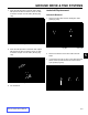


Table Of Contents
- 1 Safety - 30in Aer 4 web.pdf
- 2 Specs n Maint - 30in Aer 4 web.pdf
- Torque Specifications
- Standard Torque for Dry, Zinc Plated & Steel Fasteners (Inch Series)
- Standard Torque for Dry, Zinc & Steel Fasteners (Metric Fasteners)
- 30” Aerator Specifications
- Recommended Maintenance Schedule
- Premaintenance Procedures
- Engine Maintenance
- Fuel System Maintenance
- Electrical System Maintenance
- Drive System Maintenance
- Check Tire Pressures
- Check Wheel Hub Nuts Torque Specification
- Check Wheel Lug Nuts Torque Specification
- Check Condition Of Chains
- Check Condition Of Sprockets
- Check Transmission Output Shaft Nut Torque Specification
- Jackshaft Drive Chain Tension Adjustment
- Drive Wheel Chain Tension Adjustment
- Caster Pivot Bearings Pre-Load Adjustment
- Brake Maintenance
- Belt Maintenance
- Controls System Maintenance
- Hydraulic System Maintenance
- Tine Maintenance
- 3 Chassis - 30in Aer 4 web.pdf
- 4 Hydraulics n Engine Mountg - 30in Aer 4 web.pdf
- Hydraulics
- Checking the Transmission Expansion Tank Hydraulic Oil
- Servicing the Auxiliary Hydraulic Oil
- Changing Auxiliary Hydraulic Reservoir Fluid and Filter
- Changing Hydraulic Transmission Filters and Fluid
- Transmission Belt Replacement
- Transmission Replacement
- Hydraulic Pump Belt Removal & Installation
- Idler Arm Removal & Installation
- Hydraulic Pump Rebuild
- Hydraulic Pump Assembly
- Hydraulic Cylinder Rebuild
- Engine
- Engine Replacement
- 5 Ground Dr n Tine Systems- 30in Aer 4 web.pdf
- 6 - Electrical - 30in Aer 4 web.pdf

GROUND DRIVE & TINE SYSTEMS
5-7
Toro 30” Aerator Service Manual
5
Coring Tine Removal & Replacement
1. Remove the bolt holding the tine to the shaft (Fig.
191).
Tine Shaft Installation
1. Slide the tine axle assemblies into the trailing arm
(Fig. 192).
Note: Chains on in picture for orientation purposes
only.
Fig. 191 tine R&R
2. Replace tine. Torque bolt to 20 ft-lbs. (27 Nm)
Fig. 192 trainling arm
2. Apply Loctite
®
242 to the inner ange bearing bolts
and install the bolts through the inner ange bear-
ings. Make sure the grease ttings on the bearings
face the rear of the unit. Torque bolts to 27 ft-lbs.
(37 Nm) (Fig. 193).
Fig. 193 inner ange brg bolt install