
Operator's Manual


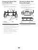


Figure62
1.Measureherefromblade
tohardsurface
2.PositionA
4.Rotatetheoppositeendsofthebladesforward.
5.Measurefromalevelsurfacetothecuttingedgeof
thebladesatthesamepositionasinstep3above.
Thedifferencebetweenthedimensionsobtainedin
steps3and4mustnotexceed3mm(1/8inch).Ifthis
dimensionexceeds3mm(1/8inch),thebladeisbent
andmustbereplaced;refertoRemovingtheBlades
(page45)andInstallingtheBlades(page46).
WARNING
Abladethatisbentordamagedcouldbreak
apartandcouldseriouslyinjureorkillyouor
bystanders.
•Alwaysreplacebentordamagedblade
withanewblade.
•Neverleorcreatesharpnotchesinthe
edgesorsurfacesofblade.
RemovingtheBlades
Bladesmustbereplacedifasolidobjectishit,ifthebladeis
outofbalanceorisbent.Toensureoptimumperformance
andcontinuedsafetyconformanceofthemachine,use
genuineTororeplacementblades.Replacementbladesmade
byothermanufacturersmayresultinnon-conformancewith
safetystandards.
1.Holdthebladeendusingaragorthickly-paddedglove.
2.For48-inchmowerdecks,removethebladebolt,
curvedwasher,andbladefromthespindleshaft(
Figure
63).
Figure63
48-inchmowerdecks
1.Sailareaoftheblade3.Curvedwasher
2.Blade4.Bladebolt
3.For52-inchmowerdecks,removethebladebolt,
curvedwasher,bladestiffener,andthebladefromthe
spindleshaft(Figure64).
Figure64
52-inchmowerdecks
1.Sailareaoftheblade4.Curvedwasher
2.Blade5.Bladebolt
3.Bladestiffener
45