
Operator's Manual
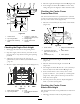


Figure66
1.CasterWheel
4.Jamnut
2.CarrierFrame
5.Balljoint
3.Frontheight-of-cutpins
2.Toraisethefrontofthedeck,loosenjamnutand
rotatethefrontpinclockwise(Figure66).
3.Tolowerthefrontofthedeck,loosenjamnutand
rotatethefrontpincounterclockwise(Figure66).
4.Positionthebladesfront-to-rear.MeasureatCand
Dlocations(Figure64)fromalevelsurfacetothe
cuttingedgeoftheblades.
5.Checktheside-to-sidelevelingofthecuttingunit.
6.Tightenthejamnuts(Figure66).
CheckingtheMowerDeck
Side-to-SideHeight
1.Adjustthereartirepressuretospecications;refer
toDriveSystemMaintenance,page30.
2.Positionthebladesside-to-side.MeasureatCand
Dlocationsfromalevelsurfacetothecuttingedge
ofbladetips(Figure67).For36inchmowerdecks
useFigure68.
Figure67
40inchMowerDeckshown
1.Measurefromalevel
surface
2.MeasurebladeatpointsC
andD
Figure68
36inchMowerDeckshown
3.ThedifferencebetweenmeasurementsCandD
shouldbenomorethan1/4inch(6mm).
ChangingtheMowerDeck
Side-to-SideHeight
Changingtheside-to-sideheightisdonebyadjustingthe
reartirepressureandcasterspacers.
1.Changethereartirepressure.Dothistothe
correspondingsidethatneedsadjustment.
2.Adjustthecasterspacer.
3.Recheckthefront-to-rearpitchandsidetoside
levelingofthecuttingunit.
MatchingHeightofCut
1.Checkthereartirepressure.
2.Settheheight-of-cuttothe4inch(101.6mm)
positionfollowingtheheight-of-cutdecal.
43