
Operator's Manual
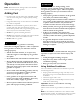


Figure18
1.Upperhandle5.Uppermountinghole
2.Rearframe
6.Lowermountingholes
3.Flangenut,(3/8inch)
7.Lowposition
4.Flangebolt,(3/8x1inch)
8.Highposition
3.Removethelowerangebolts(3/8x1inch)andange
nutssecuringthehandletotherearframe(
Figure18).
4.Pivotthehandletothedesiredoperatingpositionand
installthelowerangebolts(3/8x1inch)andthe
angenutsintothemountingholes.Tightenallange
bolts.
5.Checkthecontrolbarforcorrectadjustment.Referto
AdjustingtheControlBarinthemaintenancesection.
6.Checktheparkingbrakeadjustment.RefertoChecking
theBrakesinthemaintenancesection.
AdjustingtheFlowBafe
Themowerdischargeowcanbeadjustedfordifferenttypes
ofmowingconditions.Positionthecamlockandbafeto
givethebestqualityofcut.
1.DisengagethePTO,movethemotioncontrolleversto
theneutrallockedpositionandsettheparkingbrake.
2.Stoptheengine,removethekey,andwaitforallmoving
partstostopbeforeleavingtheoperatingposition.
3.Toadjustthebafe,loosenthenut(
Figure19).
4.Adjustthebafeandnutintheslottothedesired
dischargeowandtightenthenut.
g012676
1 2
Figure19
1.Slot
2.Nut
PositioningtheFlowBafe
Thefollowingguresareonlyrecommendationsforuse.
Adjustmentswillvarybygrasstype,moisturecontent,and
heightofgrass.
Note:Iftheenginepowerdrawsdownandthemower
groundspeedisthesame,openupthebafe.
PositionA
Thisisthefullrearposition(seeFigure20).Thesuggested
useforthispositionisafollows.
•Useforshort,lightgrassmowingconditions.
•Useindryconditions.
•Forsmallergrassclippings.
•Propelsgrassclippingsfartherawayfromthemower.
G012677
Figure20
18