
Service Manual


9-18 Power Max Service Manual
WHEEL CLUTCH
TRACTION DRIVE SYSTEM
Fig 181 MVC-878XB.jpg
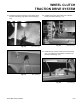
3. Remove 32-tooth sprocket gear and the thrust
washer from the shaft (Fig. 181).
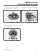
4. Remove shift collar and fl at washer from the shaft
(Fig. 182).
Note: Shift collars are marked right and left hand at
the top of the inside fl ange (A).
Note: This hole, for the spring, has been changed
to a “D” shape during 2004 for ease in
identifying the correct hole (B).
Fig 182 MVC-879X.jpg
A
B
5. Unbolt the 4 guide collars from the shaft (Fig. 183).
Fig 183 MVC-881X.jpg
Fig 184 MVC-883XWC.jpg
6. Remove the wheel clutch components from the other
end of the shaft (Fig. 184).